What Is Air Interface Slicing?
Through network-level coordinated resource allocation, air interface slicing divides the air interface time domain by period and redefines the priorities of air interface queues. In this way, some time domain resources can be reserved for key services, ensuring high reliability and deterministic latency for key services. These highlights make air interface slicing ideal for healthcare and industrial scenarios with high latency requirements.
Why Do We Need Air Interface Slicing?
In the era of digital transformation, production and manufacturing enterprises are rapidly gravitating towards IP networks, and in some cases have already started to go wireless. Devices such as robotic arms are PLC-controlled, thereby automating production. When servers in the control system deliver task instructions and collect information, ultra-high reliability is required for production services. In addition, this scenario has specific latency requirements, which, if not met, could cause production line interruption.
To address packet loss and latency issues, Huawei developed air interface slicing technology. Air interface slicing reserves uplink and downlink air interface resources in multi-AP scenarios to improve network reliability and meet latency requirements in healthcare and industrial scenarios. On a WLAN, air interfaces can be regarded as the virtual logical interfaces between APs and STAs. Wireless links established between the air interfaces allow communication between the APs and STAs. Air interface slicing technology divides a time domain period into high-reliability time slices and common time slices, and key service data is preferentially scheduled during the high-reliability time slices. Therefore, air interface slicing technology can provide deterministic latency and highly reliable networks for key services in scenarios such as industrial production, manufacturing, and healthcare.
Specifically, air interface slicing has the following advantages:
- Deterministic latency: Air interface slicing redefines the priority of air interface queues and reserves the high-reliability slicing queue with the highest priority for high-reliability services. This technology divides a time domain period into high-reliability slicing time and free contention time. APs with co-channel interference are grouped and placed in different time domains. All these mechanisms help achieve deterministic latency for the network.
- High reliability: Air interface slicing enables the air interfaces to detect interference and retransmission on the network and promptly gives warnings and corrections, thereby ensuring network reliability.
Key Technologies of Air Interface Slicing
Air interface slicing provides bandwidth reservation and fixed latency capabilities for specific services through highly reliable slicing queues, time synchronization between APs, time domain slicing, and robust scheduling technologies. In addition, interference visualization is used to quickly locate the impact of co-channel AP interference.
High-Reliability Slicing Queue
The air interface slicing feature redefines the priorities of air interface queues, and places the High Reliability (HR) queue at the position with the highest priority. In the new queue design, the HR queue with the highest priority is reserved for high-reliability services such as programmable logic controller (PLC) to ensure that these services are scheduled first.
Queue ID |
Air Interface Slicing Queue |
|---|---|
7 |
HR (high-reliability slicing) |
6 |
HR (high-reliability slicing) |
5 |
VO (voice) |
4 |
VO (voice) |
3 |
VI (video) |
2 |
BE (best effort)/BK (background service) |
1 |
BE (best effort)/BK (background service) |
0 |
VI (video) |
Time Domain Slicing
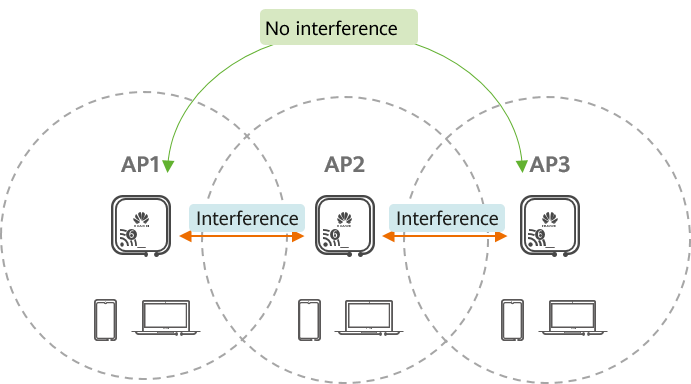
Co-channel interference between APs
In this case, the entire network-level coordinated resource allocation can be used to divide time-domain resources by period and reserve some time-domain resources for specified APs. For example, group 1 {AP1, AP3} and group 2 {AP2} are allocated to two different time slices. When group 1 sends packets, group 2 waits silently; and vice versa. The rest of the time, APs can freely contend for resources. This prevents conflicts between co-channel APs and improves the reliability of packet transmission. In addition, when resources are periodically reserved, APs can provide a deterministic transmission latency.
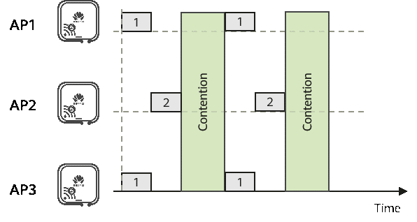
Coordinated resource allocation
Time Synchronization
Time synchronization is critical for ensuring that co-channel APs do not conflict with each other, due to time asynchronization during time domain slicing. Time synchronization is implemented by calculating the time deviation by measuring Beacon frames between APs. An AP sends Beacon frames at the interval of the target Beacon frame transmission time and fills the high-precision sending timestamp in Beacon frames. After receiving the timestamp, the neighboring co-channel AP aligns it with the locally measured timestamp by SN and compensates for the channel delay to achieve time synchronization. The following uses two APs as an example to describe the time synchronization process.
AP1 periodically sends Beacon frames. AP1 sends a Beacon frame at 

A Beacon frame sent at 


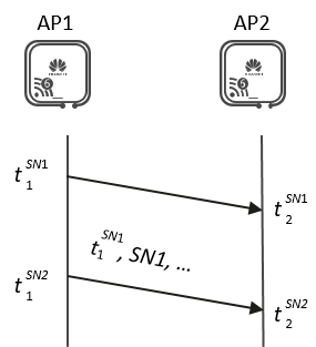
Time synchronization mechanism between APs
On a large-scale network, a master AP is specified as the reference clock of the entire network according to the network topology or AP positions. The master AP sends a Beacon frame to broadcast its high-precision timestamp and layer. All co-channel APs within the coverage area of the master AP synchronize time and update layers based on the information carried in the Beacon frame. The AP at the second layer calculates the timestamp based on the time difference with the master AP, saves the SN and timestamp, and fills in the next Beacon frame. The next-level AP calculates the time difference with the master AP based on the timestamp of the reception link. Other APs complete time synchronization layer by layer.
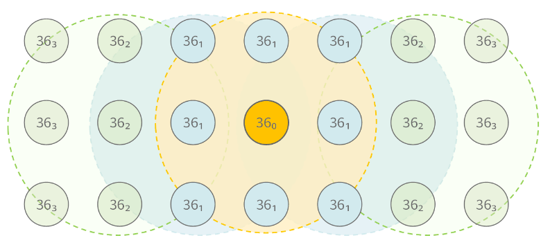
Clock synchronization on a large-scale network
Robust Scheduling
Wi-Fi packets are transmitted at a high rate over the air interface to obtain a high throughput. However, a higher packet transmission rate requires a higher signal-to-noise ratio (SNR). In other words, a higher packet transmission rate indicates inefficient anti-interference capability. The high rate increases the possibility of transmission failures, and the retransmission increases the delay. Considering the small volume of service traffic on industrial control devices, robust scheduling reduces time delays through the following improvements:
- Low-speed Modulation and Coding Scheme (MCS) preference: Packets are transmitted at more stable rates to improve transmission reliability.
- Increased transmit power: The transmit power of packets is increased so that the peer device has sufficient SNR to correctly demodulate packets.
- Hardware retransmission: Hardware retransmission technology is used to reduce the delay caused by packet retransmission.
- Limited packet sending duration: When control applications and quality inspection applications coexist, Huawei's air interface slicing dynamically determines the single-packet sending duration of different application traffic, thereby reducing the transmission delay for sending control application traffic.
Interference Visualization
Two key technologies in the WLAN channel access mechanism are Clear Channel Assessment (CCA) and Distributed Coordination Function (DCF). The CCA technology is used to evaluate the usage status of an air interface, and the DCF technology is used to implement a random backoff mechanism of air interface contention. When there are a relatively small quantity of network nodes, this decentralized access mechanism reduces costs and improves efficiency. However, as the network scale expands, the mechanisms cause various problems, such as hidden nodes, conflicts, and long waiting times for air interface access, and finally bring uncertain network delays. The preceding problems are called WLAN interference. Interference visualization can identify network interference and optimize the network based on the following principles:
- Identifying network interference: On the basis of high-precision time synchronization between APs, the central node collects the characteristics of received and sent packets (including the packet sending direction, timestamp, type, rate, delay, and number of retransmission times) on the air interface of co-channel APs. The graphical user interface (GUI) tool is used to draw an air interface fingerprint of multiple APs to clearly show how multiple co-channel APs contend for air interface resources, whether there is interference, and the interference severity.
- Optimizing network: Based on interference identification, the system adjusts related air interface parameters and performs closed-loop control. If the loop cannot be closed, an alarm is generated to give a warning and air interface interference information is retained, helping O&M personnel locate the root cause and optimize the network.
Typical Application Scenarios of Air Interface Slicing
Air interface slicing can be applied to various production scenarios, such as interconnectivity in the healthcare and industrial sectors. In actual applications, air interfaces identify key services based on Customer Premise Equipment (CPE). Installed on a wired terminal, a CPE can be connected to one or more wired terminals. Like a wireless network adapter, a CPE can convert between Wi-Fi signals and wired signals, enabling wired terminals to access a WLAN.
Healthcare Interconnection Scenario
Nowadays, a hospital typically builds a dedicated IoT network to carry healthcare services, dealing with the challenges in healthcare data collection. Wireless healthcare IoT terminals require Wi-Fi to provide different Service Level Agreements (SLAs) and reserve bandwidth for key terminals or applications. For example, nurses need to use monitors and ventilators to monitor patients' vital signs to learn patients' conditions in a timely manner. Another example is that doctors need to invoke the image materials from the Picture Archiving and Communication System (PACS) at any time during mobile ward rounds. These healthcare terminals need to be frequently moved to different wards. Air interface slicing technology can provide high-reliability and low-latency wireless networks for these terminals.
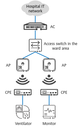
Typical networking in the healthcare interconnection scenario
Industrial Interconnection Scenario
In an industrial interconnection scenario, devices, such as robot arms and palletizers, implement automatic production under the management of the programmable logic controller (PLC) system. When servers deliver job tasks and collect information, ultra-high reliability and low latency are required to ensure production services. Air interface slicing technology reserves bandwidth resources for key services, meeting high-reliability and low-latency requirements.
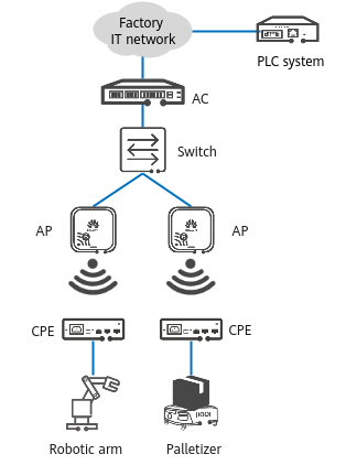
Typical networking in the industrial interconnection scenario
- Author: Wang Minghui
- Updated on: 2023-04-28
- Views: 2423
- Average rating:


