What Is CRC?
Cyclic redundancy check (CRC) is a common data transmission error detection technique commonly used in the data communication field. The transmit end calculates a check code for the data in a data frame based on a certain algorithm, appends the check code to the data frame, and sends the data frame to the receive end. The receive end verifies the correctness and integrity of the received data by repeating the calculation using the same algorithm.
Introduction to CRC
Bit errors (0 changed to 1 or 1 changed to 0) may occur in transmitted data due to transmission media faults or external interference, causing incorrect data on the receive end. To resolve this problem, the receive end needs to perform error detection on the received data and accepts the data only when it is correct.
There are many error detection methods, such as parity check, checksum check, and CRC check. Their implementation is similar: The transmit end calculates a check code for data using a certain algorithm, and sends the check code and data to the receive end. The receive end performs the same calculation to check whether the data changes.
CRC was first proposed by W. Wesley Peterson, a mathematician and computer scientist, in 1961. CRC has advantages over other error detection methods in terms of speed, cost, and correctness. Therefore, CRC has become the most commonly used error detection method in the computer information and communications fields. For example, a standard Ethernet frame ends with a 4-byte frame check sequence (FCS) for error detection.

Ethernet frame format
How Is CRC Calculation Implemented?
CRC enables the transmit end to append an R-bit check code to the K-bit data to be sent, generate a new frame, and send the frame to the receive end. When receiving the new frame, the receive end checks whether the received data is correct based on the received data and check code.

Example of data and check code
The check code needs to ensure that the generated new frame is divisible by a specific number that is selected by both the transmit end and receive end (modulo-2 division). The receive end divides the received new frame by the selected divisor. Because a number has been added before the data frame is sent to remove the remainder, there should be no remainder. If there is a remainder, an error occurs during the transmission of the frame.
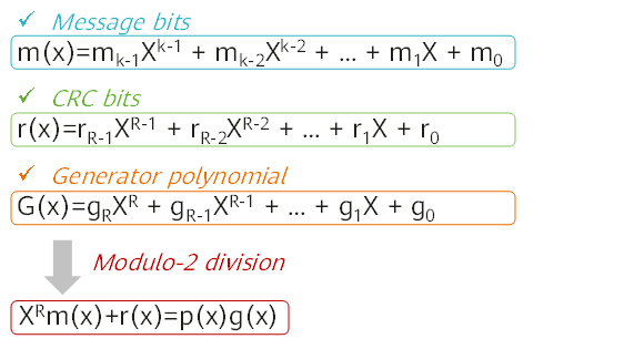
An R-bit check code is appended to the K-bit data, and the entire code length becomes N bits. This type of code is also referred to as (N,K) code. For a given (N,K) code, it can be proved that there is a polynomial g(x) whose highest power is N–K=R, and an R-bit check code can be generated based on g(x). The algorithm is based on the GF(2) polynomial arithmetic, as shown in the following figure.

CRC calculation formula
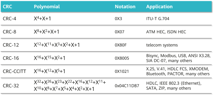
g(x) is called the generator polynomial of the check code. Different CRC generator polynomials have different error detection capabilities. To use an R-bit check code, the power of the generator polynomial must be R. The following lists some common standard polynomials.

Commonly used generator polynomials
The value of these polynomials is the divisor of modulo 2 division. Obtaining and checking the check code by using the divisor consist of the following steps:
- Before communication, the transmit end and receive end agree on a divisor P, that is, the value of a polynomial. The length of P should be R+1 bits.
- The transmit end first appends R zeros to the original K-bit data, which is equivalent to shifting the original data to the left by R bits.
- Then, a modulo-2 division operation (an XOR operation) is performed to divide the (K+R)-bit number obtained after the addition of zeros by P, and cyclic calculation is performed until an order of a remainder is less than R. The remainder is the check code. If the check code length is less than R bits, zeros are prepended to it to ensure that the length is R bits.
- The transmit end appends the R-bit check code to the original data and sends the data to the receive end.
- When receiving the data, the receive end divides the data by P using modulo-2 division. If there is no remainder, no error occurs during data transmission. Otherwise, an error occurs.
The following example illustrates the CRC calculation process:
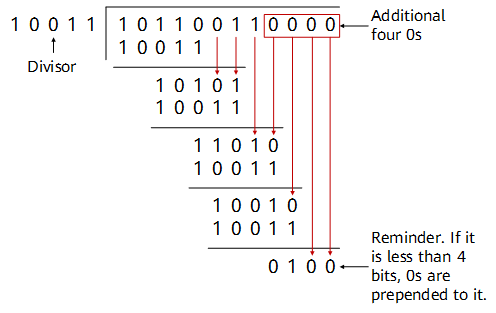
Assume that g(x) is CRC-4, which equals X4 + X + 1, and the source data M is 10110011. In this case, the divisor P is 10011.
The transmit end shifts M leftward by four bits, and divides the resulting number by P.

Example of CRC calculation at the transmit end
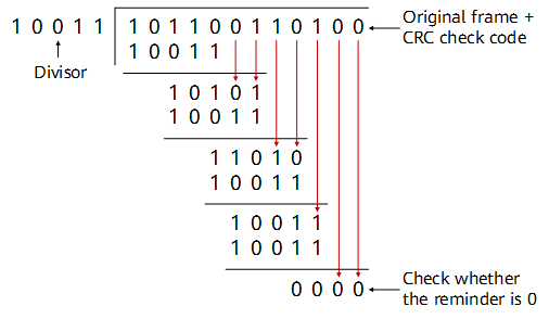
The remainder is the CRC check code, which is 0100 in this example. The transmit end appends 0100 to the original data frame 10110011 to generate a new frame 101100110100, and sends the new frame to the receive end. When receiving this frame, the receive end divides the frame by the divisor P, and considers the frame correct if the division leaves no remainder.

Example of CRC check at the receive end
How to Fix CRC Errors?
If few CRC error packets occur on an interface of a network device, no action is required. If CRC error packets are continuously generated on an interface, the possible cause is that the transmission medium is faulty. For example, the connected twisted pair or optical fiber is faulty, or the optical module on the interface does not work properly. In this case, replace the interface, optical module, or cable, and then check whether the fault is rectified.
The following uses CloudEngine series switches as an example to describe how to fix CRC errors. For details, see Troubleshooting CRC Error Packets on an Interface.
- Author: Gao Yangyang
- Updated on: 2022-12-27
- Views: 50831
- Average rating:


