What Is a Channelized Sub-interface?
A channelized sub-interface is a sub-interface of an Ethernet physical interface with channelization enabled. Different channelized sub-interfaces are used to carry different types of services, and bandwidths are configured based on channelized sub-interfaces to implement strict bandwidth isolation between different channelized sub-interfaces on the same physical interface. This prevents services on different sub-interfaces from preempting each other's bandwidths. Channelized sub-interfaces are used to reserve resources in a network slicing solution. An independent "lane" is planned for each network slice, and "lanes" cannot be changed during transmission of different network slices' service traffic. This ensures strict isolation of services on different slices, and effectively prevents resource preemption between services when traffic bursts occur.
Why Do We Need a Channelized Sub-interface?
With the emergence of diversified new services in the 5G and cloud era, different industries, services, or users pose various service quality requirements on networks. Services such as mobile communication, environment monitoring, smart home, smart agriculture, and smart meter reading require huge numbers of device connections and frequent transmission of many small packets. Other examples are live streaming, video uploading, and mobile healthcare services, which require higher transmission rates; and Internet of Vehicles (IoV), smart grid, and industrial control services, which require millisecond-level latency and near-100% reliability. Different services have different QoS requirements. To meet the requirements, the most effective method is to isolate resources for services. The simplest way to isolate resources is to differentiate services based on the isolation of physical bandwidths. However, with the continuous evolution of high-rate interfaces on routers, no type of service traffic can exclusively occupy the bandwidth of a high-rate interface in a short period of time. Therefore, a high-rate interface is split into sub-interfaces with low bandwidth to carry services, so that each sub-interface exclusively occupies bandwidth resources, preventing bandwidth resource preemption. Channelized sub-interfaces are thus introduced.
Channelized sub-interfaces are typically used to reserve resources in a network slicing solution, and a slice network using channelized sub-interfaces has the following characteristics:
- Strict resource isolation: Based on the sub-interface model, resources are reserved in advance to prevent slice services from preempting resources when traffic bursts occur.
- Small bandwidth granularity: Channelized sub-interfaces can be used together with FlexE interfaces, dividing a high-rate interface into sub-interfaces with low bandwidth. The minimum granularity is 2M, which is applicable to industry slices.
What Are the Differences Between Channelized and Common Sub-interfaces?
The main difference between channelized and common sub-interfaces lies in whether they can exclusively occupy the bandwidth.
Remaining bandwidth of a main interface = Interface bandwidth – Bandwidth sum of all channelized sub-interfaces. For example, after a 200 Mbit/s channelized sub-interface is configured on a 1 Gbit/s interface, the bandwidth of the main interface is automatically reduced to 800 Mbit/s, as shown in the following figure. A channelized sub-interface exclusively occupies the bandwidth, which cannot be preempted. In addition, resources can be reserved for services to assure the service bandwidth. However, the bandwidth of a common sub-interface can be preempted by other sub-interfaces. As such, strict bandwidth assurance cannot be provided.
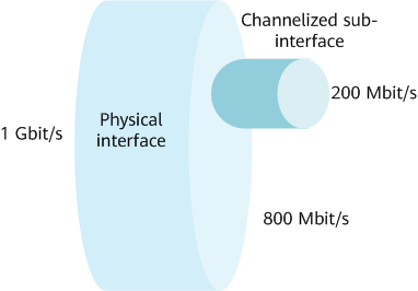
Bandwidth reduction
Channelized Sub-interface and FlexE Interface
What Is a FlexE Interface?
Flexible Ethernet (FlexE) decouples the MAC layer from the PHY layer by adding a FlexE shim layer (logical layer) between them. With FlexE, the one-to-one mapping between MACs and PHYs is no longer necessary, and M MACs can be mapped to N PHYs, thereby implementing flexible rate matching.
The PHY layer is the physical layer, which is a visible physical Ethernet port. A set of PHYs is called a FlexE group. As shown in the following figure, FlexE shim divides the PHY layer into equal timeslots, and the size of each timeslot is adjustable, for example, 1G, 1.25G, or 5G. A FlexE group flexibly allocates timeslots based on service requirements. That is, it flexibly allocates bandwidth resources and provides interfaces (collectively called FlexE clients) with different bandwidths for different users. Each interface exclusively occupies bandwidth. For example, two 100G physical interfaces are bonded to a FlexE group. If each timeslot is set to 5G, bandwidth resources can be flexibly allocated an integer multiple of 5G according to service requirements. For example, the FlexE group can be divided into three FlexE interfaces: 75G, 75G, and 50G. FlexE technology makes Ethernet interfaces "flexible."
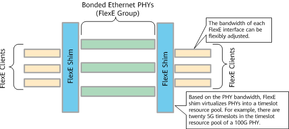
FlexE structure
FlexE technology uses FlexE shim to pool physical interface resources based on timeslots. A high-rate physical interface is flexibly divided into several sub-channel interfaces (FlexE interfaces) based on a timeslot resource pool, implementing flexible and refined management of interface resources. Bandwidth resources of each FlexE interface are strictly isolated. As such, a FlexE interface is equivalent to a physical interface and provides strict bandwidth and latency assurance.
What Are the Differences Between a Channelized Sub-interface and a FlexE Interface?
The main differences between a channelized sub-interface and a FlexE interface are as follows:
- Resource isolation effect
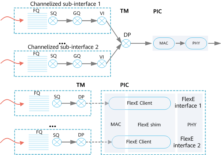
The principles for implementing resource isolation are different between a FlexE interface and a channelized sub-interface. As shown in the figure, FlexE interfaces are isolated based on timeslots between the MAC and PHY layers. Each FlexE interface has an independent MAC layer and is not affected by other FlexE interfaces when processing frames. A channelized sub-interface does not have an independent MAC layer, and the MAC layer is shared. When processing frames (such as jumbo frames), a channelized sub-interface does not process the next frame until the processing of the current frame is complete. Therefore, the resource isolation effect of FlexE interfaces is better.
In addition, each channelized sub-interface has an independent GQ/VI scheduling tree to implement strict scheduling isolation and provide strict bandwidth assurance and certain latency assurance. Channelized sub-interfaces can be used to carry networking services that require bandwidth assurance.
A FlexE interface is equivalent to a physical interface. Each FlexE interface has an independent forwarding queue and buffer. FlexE interfaces have extremely little latency interference with each other and can provide deterministic latency. They are used to carry URLLC services that have high requirements on latency SLA, such as differential protection services of power grids.
Comparison between FlexE interfaces and channelized sub-interfaces - Latency assurance effect
Due to the impact of background traffic congestion, the maximum latency increased per hop for a channelized sub-interface and a FlexE interface is as follows:
- Channelized sub-interface: The latency is increased by a maximum of 100 µs per hop.
- FlexE interface: The latency is increased by a maximum of 10 µs per hop.
Therefore, the latency of the FlexE interface is lower.These specifications are provided based on the most severe congestion scenarios, in which the total interface traffic exceeds the interface bandwidth, and traffic congestion occurs in multiple reserved resources.
- Network slice granularity
A channelized sub-interface is a fine-granularity slice, and the minimum granularity is 2M. A FlexE interface has a relatively large slice granularity, and the minimum granularity is 1G (supporting 1G, 1.25G, and 5G).
Channelized Sub-interface and Flex-channel
What Is a Flex-channel?
A flexible sub-channel (Flex-channel) refers to a service channel that is allocated independent queue and bandwidth resources based on an HQoS mechanism. Bandwidths are strictly isolated between Flex-channels, which provides a flexible and fine-granularity interface resource reservation mode.
What Are the Differences Between a Channelized Sub-interface and a Flex-channel?
Compared with a channelized sub-interface, a Flex-channel does not have a sub-interface model and is easier to configure. As such, a Flex-channel is more suitable for scenarios where network slices are quickly created on demand. In addition, a Flex-channel supports M-level bandwidth allocation granularity to meet the slice bandwidth requirements of enterprise users.
Flex-channels are typically used together with FlexE interfaces or channelized sub-interfaces, as shown in the following figure. Carriers usually use FlexE interfaces or channelized sub-interfaces to reserve large-granularity slice resources for specific industries or service types, and further use Flex-channels in the slice resources of these industries or service types to plan fine-granularity slice resources for different enterprise users. Network slices with hierarchical scheduling are used to implement flexible resource allocation and refined management.
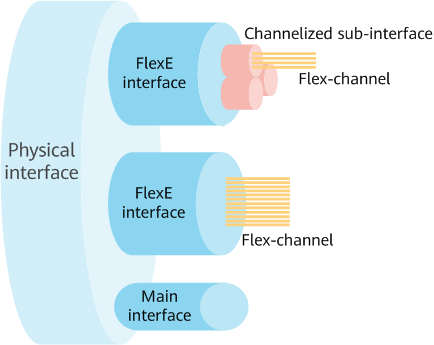
Using different interfaces together
How Does a Channelized Sub-interface Work?
What Is HQoS?
The implementation of a channelized sub-interface is related to HQoS; therefore, before learning about a channelized sub-interface, we need to understand what HQoS is.
Traditional QoS performs one-level scheduling. A single port can differentiate only services but not users. The traffic of the same priority uses the same port queue. The traffic of different users competes for the same queue resource. As a result, each type of traffic of a single user on a port cannot be differentiated. HQoS uses multi-level scheduling to differentiate traffic of different users and services in a refined manner and provide differentiated bandwidth management. As such, HQoS is a hierarchical QoS technology that uses a multi-level queue scheduling mechanism to guarantee the bandwidth of multiple services for multiple users in the DiffServ model. For more information about HQoS, watch the HQoS video.
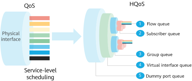
Comparison between QoS and HQoS
HQoS can implement multi-level scheduling and provide different quality services for the traffic of different users and services. However, when the traffic on a main interface is heavy, sub-interfaces preempt each other's bandwidth, which affects the scheduling of sub-interfaces and HQoS. You can configure a sub-interface and ensure that the bandwidth allocated to it cannot be preempted. In this case, the sub-interface exclusively uses bandwidth resources. Scheduling isolation is implemented for the sub-interface based on the HQoS mechanism. Such a sub-interface is a channelized one.
How Is a Channelized Sub-interface Implemented?
Channelized sub-interfaces use the sub-interface model. Based on the HQoS mechanism, they exclusively occupy the HQoS VI and GQ scheduling trees and bandwidth to implement strict scheduling isolation. As shown in the following figure, if a 1 Gbit/s interface is configured with two channelized sub-interfaces (one 200 Mbit/s and the other 300 Mbit/s), the bandwidth of the interface is reduced to 500 Mbit/s. The bandwidth reduction process is automatically implemented when the channelized sub-interfaces are enabled. In this way, the channelized sub-interfaces can exclusively use 200 Mbit/s and 300 Mbit/s bandwidths, respectively. In addition, each channelized sub-interface exclusively occupies a sub-interface scheduling tree, implementing independent queue scheduling. Therefore, services of different types can be isolated by allocating different service traffic to different channelized sub-interfaces.
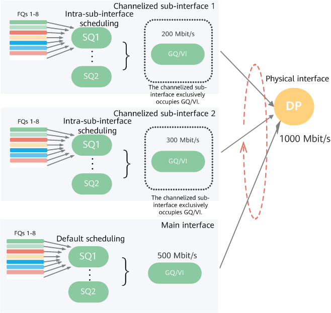
Implementation of channelized sub-interfaces
Compared with HQoS, a channelized sub-interface has management entity capabilities. It has the application scenario of a sub-interface as well as the bandwidth and management attributes of a main interface. On live networks, channelized sub-interfaces can work with a controller to manage resources, reserve resources in an E2E manner, and provide independent resources for a network slice.
- Author: Wang Jian
- Updated on: 2022-06-17
- Views: 4430
- Average rating:


