What Is Overload Control(OLC)?
Overload Control (OLC) is a mechanism that prevents CPU resources from being exhausted. OLC monitors certain CPU-bound protocol packets and tasks. According to the priorities of different services, OLC rate-limits the monitored protocol packets and tasks if the CPU usage exceeds a certain threshold. In this way, OLC not only reduces consumption of CPU resources but also prevents CPU overload from affecting normal processing of other services.
Why Do We Need Overload Control?
On a complex live network, the CPU may be overloaded if a large amount of service traffic is sent to the CPU or the CPU is attacked by unauthorized services. CPU overload will affect both the device's performance and its ability to process services.
OLC uses the multi-level leaky bucket algorithm (involving a token bucket and multi-level leaky buckets) to control the CPU-bound monitored protocol packets and tasks. OLC offers the following benefits:
- Prevents sustained overloading of the CPU, ensuring availability of device resources.
- Prevents devices from being attacked by unauthorized services, ensuring device security.
- Prevents certain services from impacting the normal processing of other services, ensuring fairness of service processing.
What Are Application Scenarios of Overload Control?
To control the monitored protocol packets and tasks in time in case of CPU overload, you can enable the OLC function. Also, you can enable the OLC function for a specified protocol or task. In addition, after the OLC alarm function is enabled, when the CPU usage reaches the OLC start threshold or falls below the OLC stop threshold, an alarm is generated.
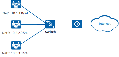
For instance, on the network shown in the following figure, users on different network segments access the Internet through the Switch. Because many users connect to the Switch, the CPU of the Switch receives a large number of protocol packets, such as ARP Request packets, ARP Reply packets, and ARP Miss packets, and frequently processes tasks such as the ARPA task. As a result, the CPU usage increases sharply, affecting service processing. The customer expects that the Switch can generate an alarm and rate-limit these protocol packets and tasks when the CPU usage exceeds a stable range, so that processing of other services will not be affected and the CPU usage is reduced to a stable range.
Now, you can configure the device as follows:
- Enable the OLC function.
- Enable the OLC function for the ARP Request, ARP Reply, and ARP Miss packets.
- Enable the OLC function for the ARPA task.
- Enable the OLC alarm function.
- Set the OLC start threshold to a stable range.

Networking diagram of OLC
How Does Overload Control Work?
OLC uses the multi-level leaky bucket algorithm to control the monitored protocol packets and tasks. A token bucket is used to determine whether the monitored protocol packets or tasks are allowed to be sent to the CPU, while multi-level leaky buckets determine the rate at which they are sent.
The OLC function takes effect once the CPU usage reaches the OLC start threshold.
Token Bucket
A token bucket is used to hold tokens, with the maximum number of tokens allowed in a token bucket representing the maximum packet processing capability of the CPU. A leaky bucket can only send packets to the CPU after being allocated tokens by the token bucket, which in turn is allocated a certain number of tokens by the system at an interval of 1 second. To control the number of packets sent to the CPU, OLC automatically adjusts the number of tokens allocated to the token bucket based on the CPU usage. That is, when the CPU usage exceeds a specified threshold, the system reduces the number of allocated tokens. After tokens in the token bucket are used up, new packets entering the leaky buckets cannot be sent to the CPU, thereby reducing the load on the CPU.
Multi-level Leaky Buckets
The analogue of a leaky bucket is a counter, which increments by 1 every time a packet enters the leaky bucket and a token is obtained for the packet. If the counter reaches the preset threshold, subsequent packets may be discarded. The counter is also decremented by 1 after a packet leaves the leaky bucket. The rate at which the counter is decremented is equivalent to the rate at which the leaky bucket sends packets to the CPU.
The multi-level leaky buckets used by OLC include the top, middle, and bottom leaky buckets. The top leaky bucket controls the leaky buckets in the entire system. Middle leaky buckets include the task leaky bucket and protocol leaky bucket. Bottom leaky buckets are associated with specific monitored protocols and tasks. According to the priorities of services, OLC assigns each leaky bucket a weight, which determines the number of resources, or tokens, that it can apply for. This mechanism ensures that different services are processed in a fair manner.
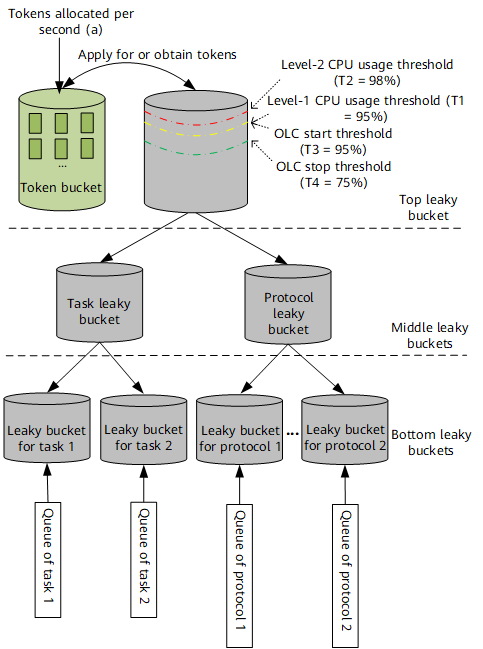
The following figure shows how multi-level leaky buckets can be implemented. The capacity of the top leaky bucket is equivalent to the maximum processing capability of the CPU. OLC takes effect when the CPU usage reaches the OLC start threshold. Before the monitored protocol packets and tasks are sent to the CPU, they enter the corresponding bottom leaky buckets, which apply for tokens from upper-level leaky buckets. These packets and tasks can be sent to the CPU only after tokens are obtained. In addition, the multi-level leaky buckets adjust the leak rate to control the rate of packets sent to the CPU.

Implementation of multi-level leaky buckets
Control parameters of multi-level leaky buckets
- Leak rate (a): This indicates the maximum number of packets that can be processed every second, which is the same as the number of tokens allocated to the token bucket every second.
- Capacity of the top leaky bucket (N): The default value is equivalent to 100% packet processing capability of the CPU.
- Level-1 CPU usage threshold (T1): The default value is 95%, indicating that the CPU usage is 95%. When the CPU usage reaches this threshold, the system starts to lower the leak rate.
- Level-2 CPU usage threshold (T2): The default value is 98%, indicating that the CPU usage is 98%. When the CPU usage reaches this threshold, the system lowers the leak rate twice as fast.
- OLC start threshold (T3): The value is the same as the level-1 CPU usage threshold. When the CPU usage reaches the OLC start threshold, the OLC start timer (10 seconds) is triggered. The OLC function is started if the CPU usage does not fall below the OLC start threshold before this timer expires.
- OLC stop threshold (T4): The value is the same as the level-1 CPU usage threshold minus 20%. The default value is 75%, indicating that the CPU usage is 75%. When the CPU usage falls below the OLC stop threshold, the OLC stop timer (20 seconds) is triggered. The OLC function is stopped if the CPU usage does not reach the OLC start threshold again before this timer expires.
- Adjustment factor (S): This parameter specifies the frequency at which the leak rate is adjusted. The smaller the adjustment factor, the faster the adjustment frequency, and vice versa. A smaller adjustment factor will allow the system to adjust more quickly to service changes but may lead t o flapping of the leak rate.
Weighted water level of multi-level leaky buckets
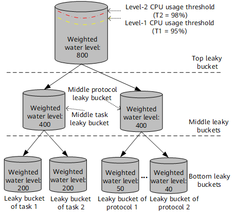
OLC assigns each leaky bucket a weight, which determines the number of resources, or tokens, that it can apply for. The resources allocated to each leaky bucket determine its weighted water level.The following figure shows an example of weighted water level allocation for multi-level leaky buckets. The initial weighted water level of the top leaky bucket is equivalent to the total number of tokens that can be applied for when the CPU usage is 95%. The weighted water level resources of the top leaky bucket then are allocated downwards to leaky buckets level by level according to weights of the leaky buckets. At each level, the sum of the weighted levels of all leaky buckets is the same as the weighted water level of the top leaky bucket.
Weighted water level allocation for multi-level leaky bucketsWater level update for multi-level leaky buckets
The water level of a leaky bucket refers to the number of packets for which the leaky bucket needs to apply for tokens. The water levels of leaky buckets at each level are updated according to the token applications and weighted water levels. The detailed water level update process is as follows:- After monitored protocol packets or tasks enter the corresponding bottom leaky buckets, tokens need to be applied for and the water levels of the bottom leaky buckets raise. Accordingly, the water levels of the middle and top leaky buckets raise by the same degree.
- The bottom leaky bucket checks whether the current water level exceeds the weighted water level. If not, tokens are successfully obtained and the packets are sent to the CPU. If so, the system applies for resources from the upper-level leaky bucket. If the water level of the upper-level leaky bucket does not exceed the weighted water level, tokens are successfully obtained and the packets are sent to the CPU.
- After packets leave the bottom leaky buckets, the water levels of the bottom, middle, and top leaky buckets fall by the same degree.
Idle resource allocation to leaky buckets that lack resources
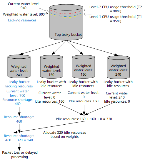
If the water level of the top leaky bucket exceeds the weighted water level, the entire system lacks resources. The system updates the water levels of leaky buckets every second and calculates the resources that the leaky buckets at each level lack. The idle resources of leaky buckets can be assigned to those that lack resources.
The idle resources of leaky buckets can only be assigned to the same type of leaky buckets, that is, protocol leaky buckets or task leaky buckets.
The following figure shows an example of idle resource allocation to a leaky bucket that lacks resources.- The system calculates the differences between the current water level and the weighted water level of each leaky bucket to find the leaky buckets with idle resources and those that lack resources.
- Idle resources of upper-level leaky buckets are allocated to those lacking resources level by level based on weights of the leaky buckets.
- If all idle resources in the system are used up and there are still leaky buckets lacking resources, excess protocol packets are discarded or tasks are delayed.
Idle resource allocation to a leaky bucket that lacks resourcesWater level threshold setting for leaky buckets
If a protocol or task leaky bucket consumes all of the resources of the top leaky bucket, the system may process other services unfairly. To prevent this, the system calculates and sets the water level threshold for a leaky bucket that lacks a lot of resources based on the resources of leaky buckets at each level. After the water level threshold is set for a leaky bucket, it is not allowed to apply for resources from the upper-level leaky buckets if the current water level of the leaky bucket is greater than its weighted water level and the water level threshold.
- Author: Fu Li
- Updated on: 2022-05-07
- Views: 4100
- Average rating:


