

What Is an Orthogonal Architecture?
An orthogonal architecture is a hardware structure that orients LPUs or interface boards orthogonally to SFUs. This eliminates the need for a backplane and its associated traces, thereby achieving high transmission rates and overcoming the line rate bottleneck in the traditional backplane architecture. In addition to featuring high scalability and a large switching capacity, an orthogonal architecture also ensures low signal attenuation. It is employed on core routers and core DC switches.
What Is an Orthogonal Architecture?
An orthogonal architecture — or to use its full name, a backplane-free orthogonal architecture — is a hardware structure that eliminates the need for a backplane by orienting a router's Line Processing Units (LPUs) or a switch's interface boards orthogonally to Switch Fabric Units (SFUs). In mathematics, two vectors are considered orthogonal if they form a 90-degree angle (perpendicular). Likewise, if LPUs or interface boards are horizontally installed and SFUs are vertically installed (or vice versa), the hardware architecture is considered orthogonal.
A real-world example is provided here to help you understand the orthogonal architecture. Assume that a car (representing signals) departs from place A. In order to reach place B as soon as possible, the car has to drive at a high enough speed (the PCB bus has to provide a high rate — 25 Gbit/s, for instance). Furthermore, the road between the two places must be as direct as possible and constructed properly (the trace between two points must be minimized, and impedance must be continuous). If there is a straight and flat highway between the two places, the car can drive at high speed (high bus rate) without consuming too much energy (low bus energy consumption). However, if the road between the two places is uneven and curved (the bus passes through multiple connectors, the trace length is long, the backplane material is not ideal, or the impedance is discontinuous), even a racing car would be unable to drive at high speed (the energy consumption is also high). In this example, the orthogonal architecture functions like the highway, providing high-speed switching channels for switching systems.
As switching links provide higher and higher speeds, the traditional backplane architecture becomes the bottleneck for improving the line rate due to a series of associated problems. To address these problems, the orthogonal architecture solution was proposed. This architecture, designed for ultra-large-capacity routers and switches, has evolved from quasi-orthogonality to orthogonality and finally to direct orthogonality.
How Did the Orthogonal Architecture Emerge?
Before the orthogonal architecture emerged, there were non-orthogonal and pseudo-orthogonal architectures in the industry.
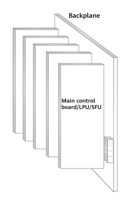
In the non-orthogonal architecture (i.e., the traditional PCB backplane architecture), all boards are inserted on the same side of a backplane and interact with each other through the passive copper traces on the backplane, as shown in Figure 1-1.
This architecture, which supports only single-sided insertion, cannot meet bandwidth and capacity evolution requirements due to it supporting only two to six planes of data switching. In addition, backplane interconnection requires long traces— leading to high loss — and cannot support high-speed or high-density signals.
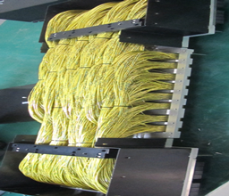
The pseudo-orthogonal architecture is similar to the orthogonal architecture in terms of appearance — the front boards are horizontally inserted and the rear boards are vertically inserted, or vice versa. The difference is that the pseudo-orthogonal architecture uses a large midplane into which all boards are inserted (instead of using orthogonal connectors for direct connection). In other words, boards in the pseudo-orthogonal architecture are still connected through the backplane traces, as shown in Figure 1-2.

This architecture expands the number of switching planes slightly compared with the PCB backplane architecture. However, it does not significantly reduce the length of traces on the backplane, meaning that the transmission rate is still limited.
Specifically, as link rates increase, the trace length between SFUs and LPUs (or interface boards) and PCB materials hinder line rate improvement. To realize ultra-high-speed data link transmission, it is necessary to maximally reduce the trace length and use more innovative PCB materials or advanced cables and optical fibers.
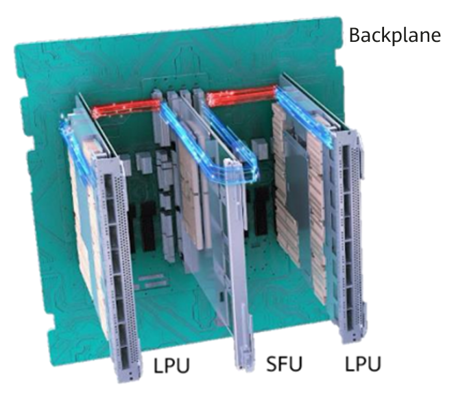
The orthogonal architecture (as shown in Figure 1-3) can effectively handle the challenge presented by high-speed switching links. The orthogonal connectors used in this architecture ensure bandwidth scalability and compatibility of SFUs, eliminate the backplane and corresponding traces, and minimize the distance between LPUs and SFUs (there is a certain distance within each connector). Consequently, there is no requirement on PCB materials used for a backplane (however, there are still some requirements on the boards' PCB materials).

How Does the Orthogonal Architecture Differ from Other Architectures?
Take Huawei routers as an example. Currently, three architectures are used: PCB backplane architecture, cable backplane architecture, and backplane-free orthogonal architecture. The following table lists the characteristics of each architecture.
Board Interoperability Architecture |
PCB Backplane |
Cable Backplane |
Backplane-Free Orthogonal Architecture |
|---|---|---|---|
Appearance |
|||
Architecture characteristics |
Traditional PCB materials |
High-speed cable + connector, fixed by structure |
No backplane. LPUs and SFUs are connected through orthogonal connectors. |
Slot capacity |
Medium. Generally < 6.4 Tbit/s |
Large. The capacity of a single slot can evolve to more than 14.4 Tbit/s. |
Large. The capacity of a single slot can evolve to more than 14.4 Tbit/s. |
Number of slots |
> 16 service slots |
20 service slots. Up to 160 service slots in a cluster |
16 service slots (matching the industry average) |
Bandwidth evolution |
Limited by the PCB backplane loss, evolution is difficult. |
Supports 112G+ SerDes. |
Supports 112G+ SerDes. |
Characteristics |
High LPU reliability and simple O&M Highest cost-effectiveness High processing efficiency |
Small signal attenuation — only 1/4 of that of traditional PCBs Supports clusters and features good scalability. High reliability and stability, and simple O&M |
Larger system capacity Smaller footprint Greater energy efficiency |
Device dimensions |
High and shallow. Installed in a cabinet with a depth less than 1 m. |
High and shallow. Usually installed in a 1 m-deep cabinet |
Low and deep. Installed in a cabinet with a depth greater than 1 m |
Typical product |
NE40E, S12700E, PTN 7900E |
NE5000E, NE9000 |
NetEngine 8000 X4, NetEngine 8000 X8, NetEngine 8000 X16 |
What Are the Key Technologies Used in the Orthogonal Architecture?
The orthogonal architecture is relatively new, emerging in recent years due to factors such as the technical maturity of orthogonal connectors, difficulty in designing efficient heat dissipation solutions for orthogonal systems, difficulty in machining large SFU PCBs, and difficulty in ensuring precision of the device structure.
- Orthogonal connectors. As they are part of a product for its entire lifecycle, orthogonal connectors are an important factor that determines whether high-speed links can be upgraded. The next-generation connectors used by Huawei support higher rates in terms of high-speed connections, crosstalk, and connection density, and can be used on core switches requiring higher rates.
- Heat dissipation solution. In the orthogonal architecture, LPUs and SFUs are installed perpendicular to each other. The entire chassis is divided into two independent spaces through the backplane. These two spaces must be completely isolated and both maintain the front-to-rear ventilation channel to dissipate heat, creating challenges in designing a heat dissipation solution. Based on multiple design concepts and extensive experience in engineering capabilities, the industry proposes three heat dissipation solutions: 1) direct ventilation front-to-back air channel, 2) cascading air channel + direct ventilation front-to-back air channel, and 3) area independent heat dissipation air channel + direct ventilation Z-shaped heat dissipation air channel + horizontal heat dissipation air channel. These solutions ensure device reliability in long-term high-speed operation.
- Machining capability of large SFU PCBs. In the orthogonal architecture, SFUs must span all service board slots in order to connect all service boards. For example, an SFU of the CloudEngine 12816 must span all 16 service board slots and two SFU slots, meaning the SFU size must be large. Before an industrial production line of large boards reaches maturity, the SFU is limited in size and can orthogonally cover only some slots. Edge slots that are not covered have to be connected through backplane traces. As a result, the pseudo-orthogonal architecture has to be used, and other parameters such as performance and heat dissipation are also affected.
- Precision of the device structure. In the orthogonal architecture, boards are inserted in two directions, the structure skew of which must be controlled. This poses high requirements on the precision of the structure design. Furthermore, achieving high-speed transmission requires connection reliability and impedance continuity — this in turn means that the structure must be highly precise. The traditional device structure oriented to the non-orthogonal architecture is unsuitable for the orthogonal architecture and needs to be improved drastically, requiring profound advances in structural design capabilities.
Where Is the Orthogonal Architecture Used?
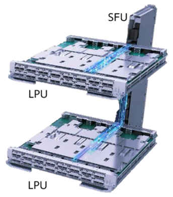
The orthogonal architecture is mainly used on Huawei's NetEngine 8000 X series routers (core nodes on metro networks). On these routers, the main control boards and LPUs are horizontally inserted, whereas the SFUs are vertically inserted. As shown in Figure 1-4, SFUs (eight in total) vertically inserted into the NetEngine 8000 X8 are connected to two main control boards and eight LPUs (which are horizontally inserted in the front of the device). In this way, the SFUs are centrally controlled and managed by the main control boards and enable data exchange between all the LPUs.

As the number of LPUs increases, the length of the SFU has to increase accordingly. For example, the NetEngine 8000 X16 provides up to 16 LPU slots and requires a 1.1 m-long SFU. Machining such large SFU PCBs involves addressing significant challenges.

- Author: Qin Xun
- Updated on: 2023-12-25
- Views: 596
- Average rating:


