What Is the Solar System Architecture?
Traditional large and mid-sized campus networks use a three-layer network architecture consisting of access, aggregation, and core layers. A large number of access switches bring challenges to network deployment and routine management. The Solar System architecture consists of a central switch and remote modules (RUs), eliminating the need for devices at the aggregation layer. In this architecture, RUs can be used as modules of central switches to expand remote interfaces without requiring planning, deployment, and management.
Background
With the rapid development of network digitalization, the traditional campus network architecture faces the following challenges:
- High costs: The development of the Internet and Internet of Things (IoT) brings more and more new types of terminals. The network needs to be expanded to connect more terminals. In the current network deployment mode, switches are deployed in extra-low voltage (ELV) rooms of each floor, and network cables connecting to APs are usually buried in walls. If more terminals need to be connected, reconstruction and re-cabling are required, resulting in high costs.
- Low bandwidth: In the post-epidemic era, the rapid development of services such as remote office and online teaching poses higher requirements on the network bandwidth. Twisted pairs cannot meet the requirements of continuous bandwidth evolution.
- Difficult management: Multi-network convergence has become a trend, and the network becomes more and more complex, making network management more difficult.
To solve the preceding problems, Huawei launches the "Solar System" architecture. It consists of a central switch and RUs distributed in offices, agile workspaces, and classrooms, making network deployment and operation more efficient. The "Solar System" architecture has the following characteristics:
- Compared with the traditional three-layer network architecture that consists of the core, aggregation, and access layers, the "Solar System" architecture is a two-layer network architecture that consists of the core and access layers. Terminals can flexibly access the network through RUs without intermediate devices, saving a large number of network cables and greatly reducing network construction costs.
- Based on the optical-electrical PoE technology, a central switch can provide 300 m long-distance PoE++ power supply for RUs. In addition, the bandwidth can be increased on demand to meet the network evolution requirements in the next 10 years.
- In the "Solar System" architecture, RUs can be used as modules of a central switch to expand remote interfaces without requiring planning or configuration, reducing the number of management nodes by 80%. In addition, iMaster NCE-Campus can be used for visualized and simplified configuration of the "Solar System" architecture, and iMaster NCE-CampusInsight can be used for intelligent O&M to present the real-time interface status and traffic statistics, improving the O&M efficiency.
Solar System architecture
Architecture Components
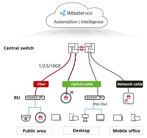
The Solar System architecture consists of a central switch and RUs. The central switch can connect to RUs through hybrid cables to provide 300 m long-distance PoE++ power supply, or through optical fibers or network cables. The central switch communicates with and manages RUs using the proprietary eXtremely Lean Discovery Protocol (XLDP).
Central Switch
A central switch manages RUs, forwards traffic in a centralized manner, and provides functions such as RU information query, configuration delivery, and firmware upgrade.
RU
An RU connects to a downlink interface of the central switch, and is used for interface expansion for the central switch. RUs can be powered directly by power adapters or by the central switch through PoE. RUs support multiple installation modes: wall-mounted, wall-embedded, and desk-mounted. An RU has the following features:
- RUs can provide PoE power supply. After being powered by the central switch, RUs can function as PoE devices to supply power to its connected terminals and APs.
- RUs are plug-and-play and configuration-free. The central switch delivers configurations to and manages the connected RUs, making RUs easy-to-use.
- An RU has only lightweight firmware deployed, which implements quicker startup than an ordinary switch.
Hybrid Cable
A hybrid cable incorporates optical fibers and copper wires within the same jacket, and can supply power to devices while transmitting data. In the Solar System architecture, a hybrid cable connects the central switch to an RU so that the switch can supply PoE power and transmit data to the RU.
XLDP
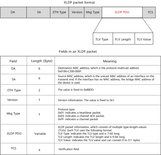
XLDP is a management control protocol used between a central switch and RUs.
The following figure shows the structure and fields of an XLDP packet.
XLDP packet format
Deployment Scenarios
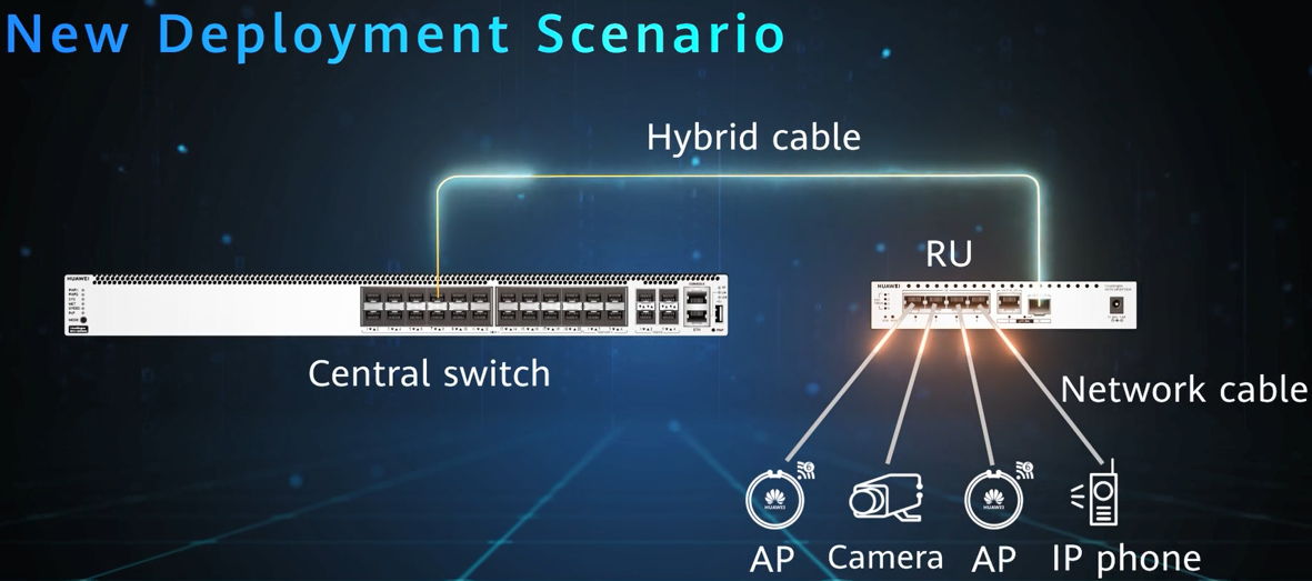
The Solar System architecture can be deployed in either a new deployment or reconstruction scenario. In a new deployment scenario, switches providing combo interfaces function as central switches and connect to RUs using second-generation hybrid cables, as well as supply power to the RUs. In a reconstruction scenario, switches providing optical ports can function as central switches and connect to RUs using optical fibers. In this scenario, RUs are powered by their local power adapters. The following figures describe the two deployment scenarios, respectively.
New deployment scenario
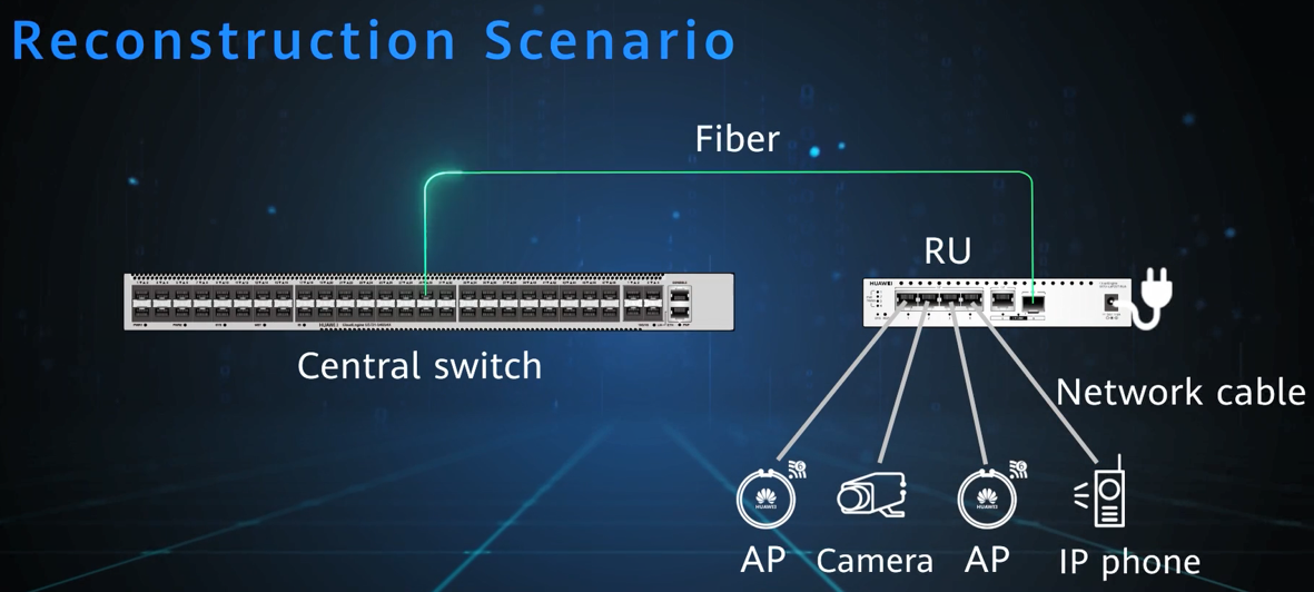
Reconstruction scenario
Application Scenarios
The Solar System architecture simplifies the network architecture, reduces management and maintenance workloads, and provides more access ports and longer power supply distance. This architecture is ideal for universities and enterprise offices.
Application in Universities
In universities, with the development of digitization, there are more and more types of terminals in classrooms, such as multi-media computers, smart large screens, APs, cameras, and broadcast systems. To connect such a large number of terminals, more access devices need to be added, which occupy classroom space and bring security risks. To deal with these problems, the network architecture needs to be simplified and provide more access ports. How can Huawei-innovated Solar System architecture help:
- One or two central switches are deployed in the equipment room of a building, and are connected to the core switch in the central equipment room of the university through dual optical fibers.
- One RU is deployed in each classroom and connected to a central switch through hybrid cables.
- Each RU connects to terminals such as APs, cameras, and PCs, and provides power for APs and cameras through PoE.
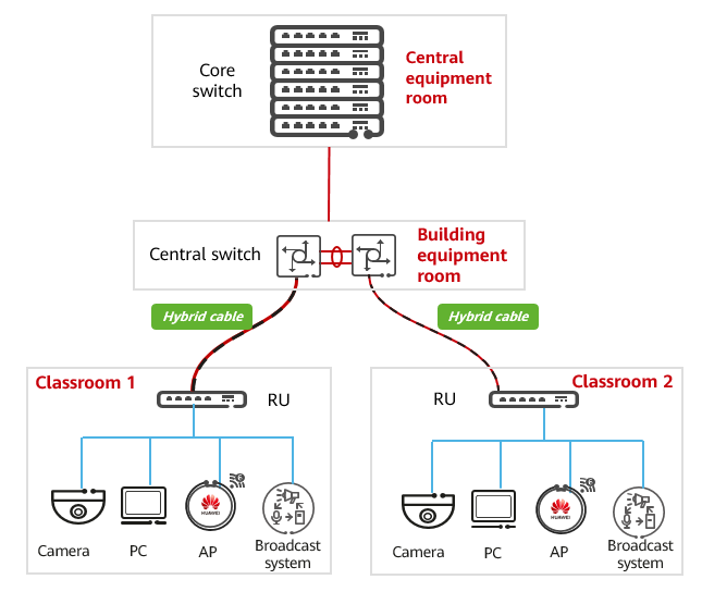
Application in universities
Application in Enterprise Offices
On an enterprise campus network, each office cubicle must have a network port and offices must be fully covered with wireless signals. The campus has multiple buildings, with a large number of labs, warehouses, and independent offices. Employee offices are scattered not only on the campus but also in each building. If a switch is deployed on each floor, network cables may not be long enough for connecting all office cubicles. Deploying two ELV rooms can solve this issue but results in high costs. In addition, deploying switches in offices may bring loud noises which severely affect the work efficiency of employees. How can Huawei-innovated Solar System architecture help:
- One desktop RU is deployed on each workspace to provide wired access for office PCs. In addition, the RU connects to APs through PoE to provide wireless access.
- One or more central switches are deployed in each office building and directly connected to offices and labs through optical fibers, solve the trouble of insufficient network cable length.
- RUs, instead of switches, are deployed in offices to reduce noises.
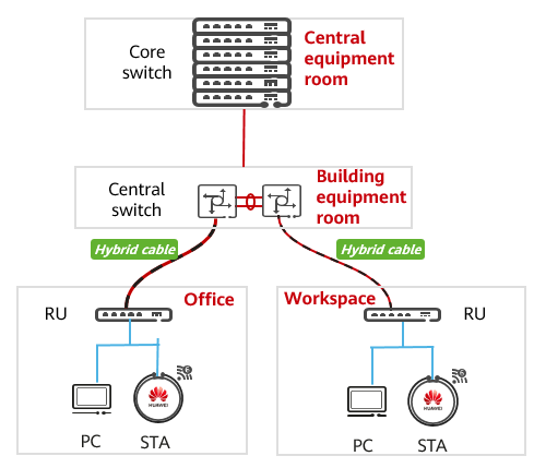
Application in enterprise offices
How Does the Solar System Architecture Work?
RU Onboarding Process
After an RU is powered on, it interacts with the central switch through XLDP to go online. During the RU onboarding process, the central switch and RU authenticate each other using certificates to ensure security. An RU can start within 10 seconds. The entire onboarding process takes no more than 30 seconds, making RUs configuration-free and plug-and-play. For the detailed RU onboarding process, see the RU Management Process.
RU Configuration and Maintenance
You can configure, maintain, and manage RUs on the central switch in a centralized manner by running commands on the central switch. Alternatively, you can perform service configuration and O&M on Huawei iMaster NCE-Campus in a graphical manner. For details about how to configure, manage, and maintain RUs, see the RU Management.
- Author: Tang Jinhua
- Updated on: 2022-12-21
- Views: 4315
- Average rating:


