What is Hot Swapping?
Hot swapping is also called power-on reseating or hot replacement. It refers to inserting or removing components such as main control boards, interface boards, and optical modules into or from a device without powering off the device. Before performing hot swapping operations, carefully read the component description documents to prevent personal injury or device damage.
What Are the Scenarios Where Hot Swapping Is Required?
Common hot swapping scenarios are as follows:
- Device capacity expansion
- Faulty component replacement
- Hardware commissioning
Hot swapping improves the fault recovery capability and flexibility of hardware capacity expansion without affecting the normal running of the device. However, not all components support hot swapping. Before removing or inserting a component, read the related operation guide carefully.
How Do I Perform Hot Swapping?
Hot swapping operations are risky because they are performed with power on. Therefore, you are advised to read the operation guide of the involved component carefully before performing hot swap operations.
Precautions
- Before inserting or removing a component, read related documents to confirm that the component supports hot swapping.
- Take ESD protection measures during the operation.
Tools
- ESD wrist strap or ESD gloves
- Phillips screwdriver
- ESD bag
Procedure
Typical hot swapping of a main control board is taken as an example to describe the basic procedure of hot swapping.
- Removing a board:
- Wear an ESD wrist strap and connect its grounding terminal to the ESD jack on the rack.
- Power off the board to be swapped.
Press and hold the OFL button on the panel of the board for six seconds till the OFFLINE indicator is on. It means that the board is powered off.
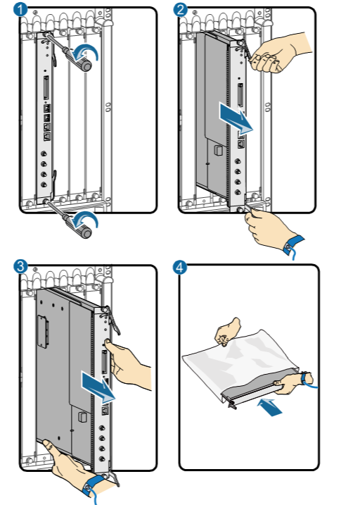
- Turn the Phillips screwdriver counter-clockwise to loosen the two captive screws on the board. See ① in Figure 1.
- Turn the ejector levers of the board outward. When they form a 45-degree angle with the panel, the board will be disconnected from the backplane. See ② in Figure 1.
- Hold the ejector levers of the board and pull out the board smoothly from the chassis along the guide rail of the slot. When the board is about 30–40 cm out of the chassis, support the lower edge of the board with one hand while holding the board panel with the other hand. Then, pull out the board smoothly from the chassis. See ③ in Figure 1.
- Put the removed board into the ESD bag.
Removing a board
- Inserting a board:
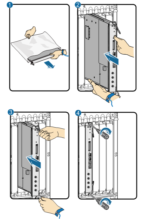
- Take a new main control board out of the ESD bag.
- Support the lower edge of the new board with one hand and hold the panel with the other hand. Then, insert the new board smoothly into the chassis along the guide rail of the slot. See ② in Figure 2. Slide the board forward until the ejector levers on the front panel of the board make contact with the chassis.
- Turn the board ejector levers outward to form 45-degree angles, and push the board into the slot with both hands. Then, turn the ejector levers inward until the board panel is in close contact with the chassis. See ③ in Figure 2.
- Turn the Phillips screwdriver clockwise to tighten the two captive screws. See ④ in Figure 2.
- Check the running status of the new board and ensure that the board is successfully inserted.
Inserting a board
- Author: Meng Yanyan
- Updated on: 2021-11-29
- Views: 3660
- Average rating:


