What Is Power over Ethernet (PoE)?
Power over Ethernet (PoE) is technology that provides both power supply and data transmission over Ethernet cables to IP terminals, such as IP phones, APs, and IP cameras.
It is also called Power over LAN (PoL) or active Ethernet.
To standardize and promote the development of the PoE technology and ensure interoperability across a broader range of powered devices (PDs) and power-sourcing equipment (PSE) from different vendors, the IEEE has released IEEE 802.3af, IEEE 802.3at, and IEEE 802.3bt.
Why Do We Need PoE?
As IP phones, network video surveillance, and wireless Ethernet devices are widely used, the demand for supplying power by the Ethernet is increasing. In most cases, terminals require a DC power supply. However, such terminals are often installed outdoors or on high ceilings far from the ground and out of reach of most power sockets. Even if a suitable power socket is available, it can be challenging to install the AC/DC converter required by terminals. Large-scale LANs typically involve many terminals, and providing the uniform power supply and management they require can be difficult. The PoE technology addresses this problem.
PoE is a wired Ethernet technology and transports both DC power and data over a single cable. It effectively provides centralized power for terminals, such as IP phones, wireless APs, chargers of portable devices, POS machines, cameras, and data collectors. PoE has the following advantages:
- Reliable: Multiple PDs are powered by a single PSE, facilitating power backup.
- Easy to deploy: Terminals can be powered over Ethernet cables, without needing external power sources.
- Standard: PoE complies with international standards, and all PoE devices use uniform RJ45 power ports and can be connected to devices of different vendors.
How Does PoE Work?
As shown in the following figure, a PoE power supply system consists of a PSE and PDs.
- PSE: a PoE device, for example, a PoE switch, that feeds power to a PD through an Ethernet cable. It provides functions such as detection, analysis, and intelligent power management.
- PD: a device that receives power, such as an AP, portable device charger, POS machine, or camera. PDs are classified into standard and nonstandard PDs depending on whether they conform to IEEE standards.
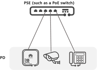
Components in a PoE power supply system
PoE Power Supply Mode
According to the IEEE standards, PSEs are classified into midspans and endpoints. Midspan indicates that the PoE module is installed outside the device, whereas Endpoint indicates that the PoE module is integrated into the device. Huawei CloudEngine S series PoE switches have PoE modules integrated inside, so they are PSE endpoints.
PSE endpoints have two power supply modes: Alternative A (line pairs 1/2 and 3/6) and Alternative B (line pairs 4/5 and 7/8).
In Alternative A mode, a PSE provides power to a PD over data pairs 1/2 and 3/6. The pair 1/2 acts as the negative polarity, while the pair 3/6 acts as the positive polarity. 10BASE-T and 100BASE-TX interfaces use data pairs 1/2 and 3/6 to transmit data, and 1000BASE-T interfaces use all four data pairs to transmit data. As DC power and data frequency are independent of each other, power and data can be transmitted over the same pair.
In Alternative B, a PSE provides power to a PD over spare pairs 4/5 and 7/8. The pair 4/5 acts as the positive polarity, while pair 7/8 acts as the negative polarity.
According to the IEEE standards, the two power supply modes cannot be used together. That is, a PSE can work in only one mode. However, PDs must support both modes.
PoE Power Supply Negotiation
After a PSE is powered on and connected to PDs, they start power supply negotiation.
- PD detection: The PSE periodically transmits a low voltage with limited current through its interfaces in order to detect PDs. If the PSE detects a resistance ranging from 19 kΩ to 26.5 kΩ, IEEE 802.3af- or 802.3at-compliant PDs are connected to the PSE. Low voltages for detecting this range of resistance are often 2.7 V to 10.1 V, and the detection interval is 2 seconds.
- Power supply capability negotiation: The PSE identifies the PD types, and negotiates the power to be supplied by parsing the detected resistance or exchanging Link Layer Discovery Protocol (LLDP) messages.
- Start to supply power: The PSE starts to provide a low voltage to the PDs in less than 15 μs, which is then raised to the full 48 V DC eventually.
- Normal power supply: After the voltage is reached to 48 V, the PSE provides stable and reliable 48 V DC power to the PDs. The PoE power output to all PDs does not exceed the maximum capacity of the PSE.
- Disconnection of power supply: The PSE keeps detecting the input current of PDs while providing power. Upon detecting that the current of a PD falls below the minimum value or increases sharply, the PSE stops providing power to this PD and re-enters the PD detection procedure. This situation occurs when a PD is disconnected from the PSE, encounters a power overload or short circuit, or its power consumption exceeds the power supply capacity of the PSE.
LLDP Power Capability Negotiation
IEEE 802.3 defines an optional type-length-value (TLV) — Power via Media Dependent Interface (MDI) TLV. This TLV is encapsulated into LLDP packets for discovering and advertising MDI power capabilities. When the PSE detects a PD, they periodically exchange LLDPDUs carrying the Power via MDI TLV to negotiate power supply parameters.
The Power via MDI TLV format for S series switches.
Power via MDI TLV Defined in IEEE 802.3
The Power via MDI TLV is composed of a two-byte TLV packet header and a 12-byte TLV information field, as shown in the following figure.

TLV packet format defined by IEEE 802.3
The following tables describe fields in Power via MDI and Extended Power via MDI.
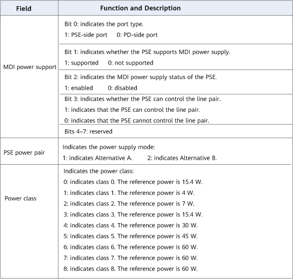
Fields in Power via MDI
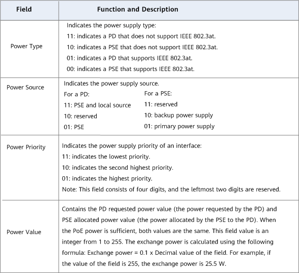
Fields in Extended Power via MDI
Power via MDI TLV Defined by Huawei
The Power via MDI TLV defined by Huawei is composed of a two-byte TLV packet header and a four-byte TLV information field, as shown in the following figure.

Power via MDI TLV packet format defined by Huawei
The following describes fields in TLV packets.
- TLV Type: indicates the TLV type and occupies one byte. The value 1 indicates the power supply mode supported by the PD, while the value 2 indicates the current power supply mode of the PD.
- TLV Length: indicates the length of the TLV information field and occupies one byte. The value 4 indicates that the TLV information field occupies four bytes.
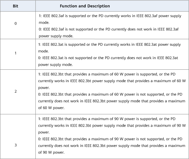
- TLV Value: indicates the TLV value. This field occupies 4 bytes and is composed of 32 bits. The following figure describes the meanings of bits 0, 1, 2, and 3. Bits from 4 to 31 are reserved.
Bits in the TLV Value field
What Are PoE Standards?
As mentioned above, the IEEE releases IEEE 802.3af, IEEE 802.3at, and IEEE 802.3bt power supply standards to standardize PoE to ensure interoperability across a broader range of PDs and PSEs from different vendors. What is the difference between the three standards?
The first of these standards, IEEE 802.3af, also known as PoE, was ratified in June 2003. As an extension of the Ethernet standard, the IEEE 802.3af standard defines PoE power supply for devices, as well as the power that a PSE can deliver and the power that a PD can receive. According to the IEEE 802.3af standard, a PSE can provide up to 15.4 W DC power on each port.
As some power dissipates in cables, only 12.95 W is assured to be available at PDs. In October 2009, the IEEE 802.3at standard, also named PoE+, was ratified, which is backward-compatible with IEEE 802.3af. It increases the maximum PoE power output to 25.5 W to satisfy the need for more power to support a wider variety of terminals.
In September 2018, the IEEE 802.3bt standard was released to further expand the power capabilities. It is also known as PoE++ or 4PPoE. This standard introduces two additional power types: up to 51 W delivered power (Type 3) and up to 71.3 W delivered power (Type 4). Additionally, support for 2.5GBASE-T, 5GBASE-T and 10GBASE-T is included. This development expands the use of applications such as high-performance wireless access points and surveillance cameras.
The following compares the three standards.
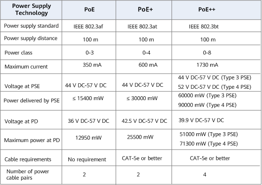
Technical specifications of PoE standards
Which Huawei Devices Support PoE?
Some models of Huawei S series campus switches, access controllers (ACs), and access routers (ARs) support PoE power supply. Whether a device supports PoE is determined by the hardware. Upgrading the software cannot change a PoE-incapable device to PoE-capable. Take Huawei S series campus switches as examples. PoE-capable switches are called PoE switches and usually deployed at the access layer. They use built-in or external PoE power modules to provide power for terminals. Modular switches with PoE-capable chassis and cards can function as PoE switches. PoE-capable fixed switches can provide PoE power after being powered on.
For details about PoE-capable S series campus switches, ACs, and ARs, see AR Series Access Routers, respectively.
- Author: Gu Suqin
- Updated on: 2023-09-01
- Views: 10202
- Average rating:


