What Is BFD?
Bidirectional Forwarding Detection (BFD) is a fast fault detection mechanism based on RFC 5880. After a BFD session is established between two systems, BFD packets are periodically sent over the path between the two systems. If one system does not receive BFD packets within a specified period, a fault has occurred on the path. After detecting the link fault through BFD, the upper-layer protocol can take measures to promptly rectify the fault.
Why Do We Need BFD?
To minimize the impact of device faults on services and enhance network reliability, a network device must be able to quickly detect faults in communication with adjacent devices. Measures can then be taken to promptly rectify the faults to ensure service continuity.
In practice, hardware detection is used to detect link faults. For example, Synchronous Digital Hierarchy (SDH) alarms are used to report link faults. However, not all media provides the hardware detection mechanism. In this case, applications use the Hello mechanism of the upper-layer protocol to detect faults, which takes usually seconds. This long detection period causes severe packet loss when traffic is transmitted at gigabit rates. On a Layer 3 network, the Hello mechanism cannot detect faults for all routes, such as static routes. This means that a fault between interconnected systems is difficult to locate.
BFD addresses these issues and provides fast fault detection independent of media and routing protocols. BFD is useful because it can:
- Implement light-load fault detection, which takes only milliseconds, enhancing reliability.
- Quickly detect a broad range of faults, including interface, data link, and forwarding engine faults.
- Provide uniform detection for all media and protocol layers in real time, without depending on hardware.
Typical BFD Application Scenarios
Generally, BFD is not used independently. Instead, it is used together with the interface status or routing protocols (such as static routing, OSPF, IS-IS, and BGP). This section describes two typical application scenarios of BFD. For other application scenarios, see Application Scenarios for BFD.
Association Between the BFD Session Status and the Interface Status
BFD for process interface status (PIS) associates the BFD session status with the interface status. This allows interfaces to be more sensitive to link faults and minimizes the impact of faults on indirectly connected links. When detecting a link fault, a BFD session immediately sends a Down message to the corresponding interface. The interface enters the BFD Down state and only processes BFD packets.

Association between the BFD session status and the interface status
As shown in the figure, SwitchA and SwitchB are directly connected at Layer 3, with transit devices being deployed between them. When the link between the transit devices is faulty, SwitchA and SwitchB will take a long time to detect the fault. This will slow down route convergence and increase service interruption time. To prevent this, a BFD session is configured on SwitchA and SwitchB. The BFD session status is associated with the interface status. When a link fault is detected, the BFD session immediately sends a Down message to the corresponding interface and the interface enters the BFD Down state.
BFD for OSPF
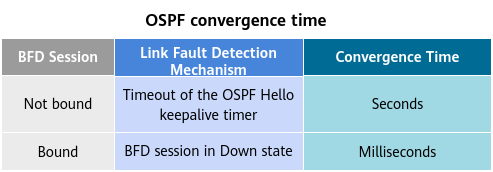
A link failure or topology change may lead to route recalculation. Therefore, the convergence time of routing protocols must be shortened as much as possible to improve network performance. A feasible solution is to quickly detect link faults and immediately notify routing protocols of the faults.
BFD for OSPF associates a BFD session with OSPF. The BFD session quickly detects a link fault and notifies OSPF of the fault. OSPF then quickly responds to the network topology change. The following figure shows the OSPF convergence time.
OSPF convergence time
BFD for OSPF
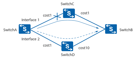
As shown in the figure, SwitchA establishes OSPF neighbor relationships with SwitchC and SwitchD. The outbound interface in the route from SwitchA to SwitchB is interface 1. Packets from SwitchA are sent to SwitchB through SwitchC. When the OSPF neighbor is in Full state, the system instructs BFD to create a BFD session.
If a fault occurs on the link between SwitchA and SwitchC, the BFD session detects the fault and notifies SwitchA. SwitchA processes the neighbor Down event and recalculates the route. Interface 2 then becomes the new outbound interface in the route. Packets from SwitchA are sent to SwitchB through SwitchD.
How Does BFD Work?
Two systems establish a BFD session and periodically send BFD packets along the path between them. If any system does not receive BFD packets from its peer within a specified period, the BFD session transitions to the Down state and the system considers the path with the peer is faulty.
This section describes how BFD works from three dimensions: BFD fault detection mechanism, BFD session establishment process, and BFD session establishment mode.
BFD Fault Detection Mechanism
Two network devices establish a BFD session to monitor the path between them and serve upper-layer applications. BFD does not provide neighbor discovery. Instead, BFD obtains information about neighbors from the upper-layer applications it serves. After two devices establish a BFD session, they periodically send BFD packets to each other. If a device does not receive a response within a set time limit, the device considers the forwarding path faulty. BFD then notifies the upper-layer protocol of this fault.
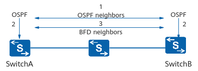
The following figure shows how a BFD session is created when OSPF and BFD are used together.
BFD session setup
In this figure, OSPF and BFD are both configured on SwitchA and SwitchB. The process of establishing a BFD session is as follows:
OSPF uses the Hello mechanism to discover neighbors and establishes a neighbor relationship.
OSPF notifies BFD of neighbor information, including source and destination addresses.
BFD sets up a session based on received neighbor information.
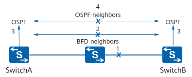
After the BFD session is established, BFD starts to monitor the link and responds quickly to any link fault.
Link fault detection by BFD
The process is described as follows:
The monitored link fails.
BFD quickly detects the link fault and changes the BFD session status to Down.
BFD notifies the local OSPF process that the neighbor is unreachable.
The local OSPF process ends the OSPF neighbor relationship.
BFD Session Setup
A BFD session has the following statuses: Down, Init, Up, and AdminDown. The State field in a BFD packet indicates the session status. The system changes the session status based on the local session status and the received session status of the peer.
- Down: A BFD session is in the Down state or a request has just been sent.
- Init: The local end can communicate with the remote end, and the local end expects the BFD session to go Up.
- Up: A BFD session is successfully established.
- AdminDown: A BFD session is taken down administratively.
The BFD state machine implements a three-way handshake for BFD session setup or deletion to ensure that the two systems detect the status change. The following figure shows BFD session establishment to describe the state machine transition process.
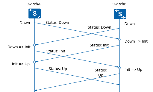
BFD session setup
SwitchA and SwitchB each start BFD state machines. The initial status of a BFD state machine is Down. SwitchA and SwitchB send BFD packets with the State field set to Down to each other. If BFD sessions are configured statically, the values of Remote Discriminator in BFD packets are specified. If BFD sessions are configured dynamically, the value of Remote Discriminator is 0.
After receiving the BFD packet with the State field set to Down, SwitchB changes the BFD session status to Init and sends a BFD packet with the State field set to Init.
After the local BFD session status of SwitchB changes to Init, SwitchB no longer processes the received BFD packets with the State field set to Down.
The BFD session status change on SwitchA is similar to that on SwitchB.
After receiving a BFD packet with the State field set to Init, SwitchB changes the local BFD session status to Up.
The BFD session status change on SwitchA is similar to that on SwitchB.
BFD Session Establishment
BFD sessions can be established in either static or dynamic mode. Static and dynamic BFD sessions differ in that local and remote discriminators are configured differently. BFD sessions are differentiated by local and remote discriminators in packets.
Static establishment
BFD session parameters, including the local and remote discriminators, are manually specified on the CLI. A request for BFD session establishment is distributed manually.
Dynamic establishment
When a BFD session is established dynamically, the system processes the local and remote discriminators as follows:
Dynamically allocated local discriminator
When an application triggers the establishment of a dynamic BFD session, the system sets the local discriminator of the BFD session. Then the local system sends a BFD packet with a remote discriminator of 0 to the remote system for BFD session negotiation.
Self-learned remote discriminator
When one end of a BFD session receives a BFD packet with the remote discriminator of 0, it checks the BFD packet. If the packet matches the local BFD session, this end learns the value of the local discriminator in the received BFD packet to obtain the remote discriminator.
One-Arm BFD Echo
In addition to association with other protocols, BFD has a special scenario: one-arm BFD echo.
The one-arm BFD echo function checks the connectivity of the forwarding link by looping back packets. You can use the BFD Echo function when one of two directly connected devices does not support BFD.
You need to configure one-arm BFD echo on the BFD-capable device. This device sends an Echo Request packet to the remote device that does not support BFD, which then sends this packet back along the same path. In this way, the BFD-capable device can detect connectivity of the forwarding link. The one-arm BFD echo function applies only to single-hop BFD sessions.

One-arm BFD echo
As shown in the figure, SwitchA supports BFD, but SwitchB does not. One-arm BFD echo is configured on SwitchA. Once SwitchB receives a BFD Echo packet from SwitchA, it loops back the packet at the network layer, quickly detecting the connectivity of the single-hop path between SwitchA and SwitchB.
- Author: Sun Hongye
- Updated on: 2021-09-30
- Views: 31517
- Average rating:


