What Is Enhanced Media Delivery Index (eMDI)?
Enhanced Media Delivery Index (eMDI) is a network quality monitoring and fault demarcation solution designed for video and audio services. It can monitor specified service packets on each node of an IP network in real time, and quickly demarcate the faulty network segment based on the monitoring results provided by one or more nodes.
Why Do We Need eMDI?
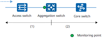
- Single-node deployment: As shown in the the following figure, eMDI is deployed on a single node (known as the monitoring point) to locate faults on the upstream and downstream network segments of this node.
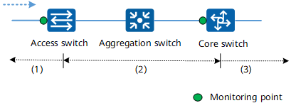
Single-node deployment of eMDI - Two-node deployment: As shown in the following figure, eMDI is deployed on two edge nodes, which are the access switch and core switch. In this case, eMDI can demarcate faults on the downstream network segment of the access switch, the network segment between the access switch and core switch, and the upstream network segment of the core switch.
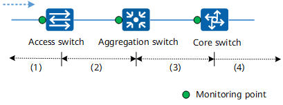
Two-node deployment of eMDI Multi-node deployment: As shown in the following figure, eMDI is deployed on three or more nodes. In this case, eMDI can demarcate faults on the downstream network segment of the access switch, the network segment between the access switch and aggregation switch, the network segment between the aggregation switch and core switch, and the upstream network segment of the core switch. For example, if eMDI detects packet loss on the aggregation switch and core switch but not on the access switch, it determines that the fault occurs on the network segment between the access switch and aggregation switch.
Multi-node deployment of eMDI
What Are the eMDI Monitoring Indicators?
An eMDI-enabled switch obtains monitoring indicator statistics from devices at a specified monitoring interval, and periodically sends the statistics to the NMS. eMDI supports quality monitoring and fault demarcation for services transmitted over TCP and UDP. The methods of collecting monitoring indicator statistics differ between UDP and TCP services.
UDP services
Monitoring indicator statistics about UDP services are calculated based on Real-time Transport Protocol (RTP) packets. RTP is a transport layer protocol designed for end-to-end and real-time transmission of services. It is widely used in communication and entertainment systems that involve streaming media, such as live video, streaming television, and video teleconference applications. An RTP packet consists of a header and a payload. The PT field in the RTP header is analyzed to determine the service type. The packet loss rate and out-of-order packet rate are calculated based on the sequence number in the RTP header. The jitter is calculated based on the timestamp in the RTP header.
TCP services
TCP is a connection-oriented transport layer protocol that provides reliable, ordered, and error-checked delivery of a stream of bytes. Monitoring indicator statistics about TCP services are calculated based on TCP packets. The average rate is calculated based on the length of TCP packets transmitted within a monitoring interval. The upstream and downstream packet loss rate is calculated based on the sequence number in the TCP header. The average upstream and downstream two-way delay is calculated based on the timestamp and serial number in the TCP header.
The following figures list the eMDI monitoring indicators.
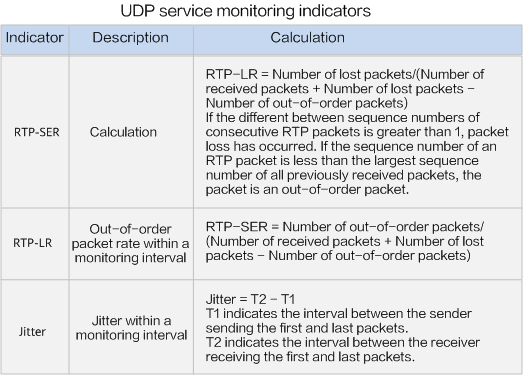
UDP service monitoring indicators
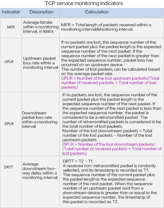
TCP service monitoring indicators
What Are Application Scenarios of eMDI?
Monitoring Quality of Video Surveillance Services
In a video network O&M solution, IP cameras (IPCs) are expected to be online and in good working order for video surveillance. For complex networks with multiple systems, if IPCs go offline or experience issues such as packet loss, the fault may be difficult to demarcate and troubleshoot. Additionally, the network O&M cost is high. These factors hinder smooth construction of the video surveillance network.
On the video surveillance network shown in the following figure, if service quality deterioration is detected by the Video Cloud Node (VCN), you can deploy eMDI on the access switch, aggregation switch, and core switch through the NMS to monitor service flows, collect monitoring indicator statistics, and demarcate faults.
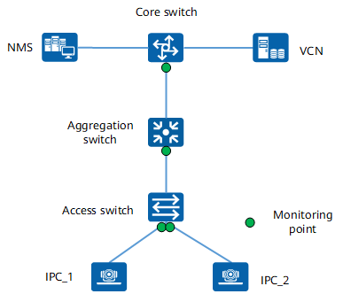
Deployment of eMDI in a video surveillance scenario
Monitoring Quality of IPTV Services
Internet Protocol television (IPTV) services have become a major source of revenue for carriers. Accordingly, monitoring quality of video and audio services is becoming increasingly important. Packet loss, out-of-order packet rate, and jitter are three key factors that affect quality of video and audio services. Artifacts or pixelation may occur on a terminal even if the packet loss rate or out-of-order packet rate is less than 1/10000, and a small amount of jitter may cause a black screen. These problems will seriously affect the revenue and reputation of carriers.
On the IPTV network shown in the following figure, if the service quality deteriorates, you can deploy eMDI on the access switch, aggregation switch, or core switch through the NMS. eMDI can then monitor service flows, collect monitoring indicator statistics, and demarcate faults.
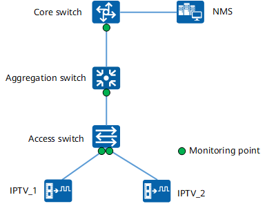
Deployment of eMDI in an IPTV scenario
How Does eMDI Work?
After eMDI is deployed on a switch, the switch periodically reports monitoring indicator statistics and threshold exceeding alarms to the NMS for real-time analysis.
When service quality deterioration is detected, you can obtain packet information about service flows, such as the source and destination IP addresses, and deploy eMDI on the switch directly or through the NMS. The following figure shows the eMDI interaction process.
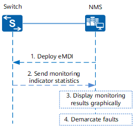
eMDI interaction process
The eMDI interaction process is described as follows:
- O&M personnel deploy eMDI on switches. This is done either directly on the switches or through the NMS.
- The switch deployed with eMDI periodically sends monitoring indicator statistics to the NMS through HTTP2+Protobuf interfaces.
- The NMS summarizes the monitoring indicator statistics of each switch and graphically displays the monitoring results.
- The O&M personnel quickly demarcate the faulty network segment based on the graphical monitoring results.
Statistics about monitoring indicators of target flows are collected by an eMDI instance, which is a basic unit of eMDI. Each eMDI instance is composed of the target flow, monitoring interval, lifetime, and alarm threshold.
- Author: Li jiyuan
- Updated on: 2021-09-30
- Views: 5019
- Average rating:


