What Is A-FEC?
Adaptive Forward Error Correction (A-FEC), an enhancement of FEC, is a data coding technology that increases the reliability of data communication. It classifies traffic, identifies specific data flows, adds redundant packets that contain verification information, and verifies packets at the receive end. If a packet is lost or damaged during transmission, a redundant packet can be used to recover it. In addition, the receive end collects statistics on the packet loss rate in real time and sends the statistics to the transmit end. The transmit end then flexibly adjusts the number of redundant packets according to the packet loss rate, implementing self-adaptation based on forward error correction.
Why Is A-FEC Required?
Instant applications, such as voice calls, video conferences, and live streaming, have stringent requirements on delay and packet loss. When packet loss occurs on the network, frame freezing and artifacts may occur in video applications, which severely affects user experience. In most cases, when the packet loss rate reaches 1%, the problem becomes obvious; when the packet loss rate reaches 10%, applications are almost unavailable. A-FEC optimizes packet transmission. It classifies traffic, identifies specific data flows, adds redundant packets that carry verification information to the original packets, and decodes the received packets at the receive end to recover the lost packets. A-FEC can ensure smooth video playback even when the packet loss rate reaches 30%.
How Does A-FEC Work?
Applications that have stringent requirements on delay and packet loss, such as audio and video applications, use UDP as the transport protocol to ensure low delay and reduce the impact of TCP handshake and retransmission. However, UDP cannot provide reliable transmission as TCP does, leading to packet loss during transmission.
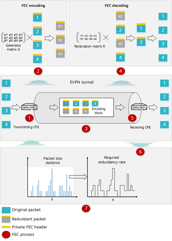
To solve this problem, when the transmit end sends data, A-FEC performs FEC encoding on the data to generate backup data, that is, redundant packets, and sends the backup data along with the original data to the receive end. In this way, even if packet loss occurs during transmission, the receive end can perform FEC decoding based on redundant packets and recover the lost packets to implement forward error correction. Finally, the receive end collects statistics on the packet loss rate during packet transmission in real time and sends the statistics to the transmit end. The transmit end then calculates the required redundancy rate based on the packet loss rate and flexibly adjusts the number of redundant packets. This implements self-adaptation of the number of redundant packets and the packet loss rate. The following figure shows the A-FEC working process.

A-FEC working process
The A-FEC working process is described as follows:
- The transmitting customer-premises equipment (CPE) receives traffic packets and identifies the packets that require packet loss mitigation.
- The transmitting CPE performs FEC encoding on original packets.
- The transmitting CPE encapsulates original packets with a private FEC header and sends the packets.
- The transmitting CPE accumulates multiple original packets as an encoding block, and encodes the original packets in the encoding block using FEC to generate FEC redundant packets. The encoding end can generate multiple redundant packets for multiple packets based on the encoding matrix (that is, generator matrix) algorithm.
- Original packets and redundant packets are transmitted on the network. In case of poor network condition, both original packets and redundant packets may be lost.
- The receiving CPE performs FEC decoding on the received original packets and redundant packets.
- The receiving CPE receives packets, detects whether packet loss occurs, and performs FEC decoding. It calculates a decoding matrix (restoration matrix) based on the encoding matrix and received packets, and recovers lost packets (if any) based on the decoding matrix and received packets. The lost packets in an encoding block can be recovered as long as the lost packets are fewer than the received redundant packets.
- After the receiving CPE completes decoding, it recovers the lost packets and removes the private header.
- The receiving CPE sends the recovered packets to other devices at the receive end in sequence.
- The receiving CPE collects packet loss statistics in real time and sends the statistics to the transmitting CPE.
- The transmitting CPE processes packets based on the received packet loss information.
- It calculates the required redundancy rate based on the packet loss information.
- It calculates the number of redundant packets required for next data transmission based on the required redundancy rate.

A-FEC process
In addition to A-FEC, Determined FEC (D-FEC) can be used to optimize packet transmission.
Huawei FEC supports the following algorithms for generating redundant packets:
- D-FEC: Redundant packets are generated at a fixed redundancy rate.
- A-FEC: Redundant packets are dynamically generated based on the packet loss information returned by the decoding end.
A-FEC vs. D-FEC
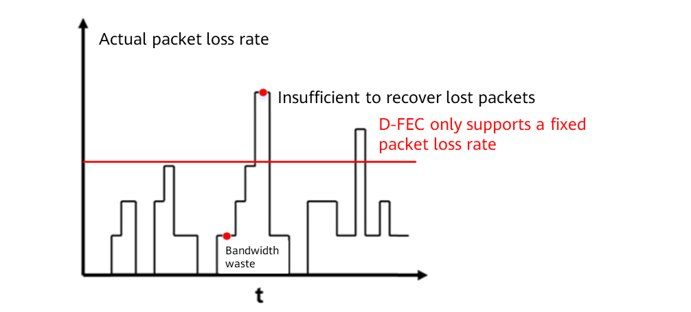
A-FEC is an improvement over D-FEC, and solves the problems of D-FEC, such as bandwidth waste and failures to recover lost packets in case of a high packet loss rate. D-FEC only supports a fixed packet loss rate, leading to a fixed number of redundant packets calculated based on the loss rate. However, the packet loss rate on the actual network keeps changing. When the actual packet loss rate is higher than the configured one, the number of required redundant packets exceeds the number of redundant packets generated by the transmit end. As a result, the number of redundant packets is insufficient to recover lost packets. When the actual packet loss rate is far lower than the configured one, the number of redundant packets generated by the transmit end exceeds the number of required redundant packets, wasting bandwidth. In contrast to D-FEC, A-FEC dynamically generates redundant packets based on the packet loss information sent by the receive end, which solves the problems of D-FEC. However, because of the detection of packet loss information and dynamic adjustment of redundant packets, A-FEC requires a certain response time when the network packet loss rate changes.

Problems of D-FEC
Different FEC technologies can be used to optimize packet transmission based on the bandwidth. If the network bandwidth is sufficient, the network quality is poor, and the packet loss rate keeps changing, use D-FEC to improve application experience. If the network bandwidth is low, the network quality is poor, and the packet loss rate does not fluctuate greatly, use A-FEC to improve application experience.
Item |
A-FEC |
D-FEC |
|---|---|---|
Packet loss rate |
Automatic detection |
Manual configuration |
Number of redundant packets |
Adjusted in real time based on the packet loss rate |
Unchanged |
Low packet loss rate |
Bandwidth saving |
Waste of bandwidth |
High packet loss rate |
The number of redundant packets is sufficient to recover lost packets. |
The number of redundant packets is insufficient to recover lost packets. |
Fast changing packet loss rate |
Temporary packet loss |
No packet loss |
How Is FEC Used in SD-WAN?
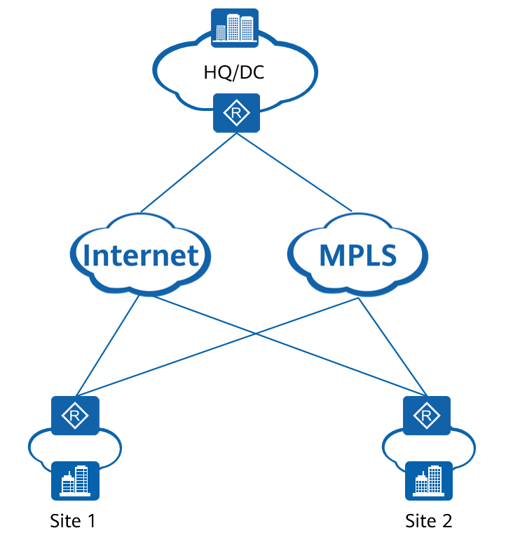
In enterprise SD-WAN networking, shown in the following figure, a typical application scenario of FEC is video conferencing. A video conferencing server is deployed at the HQ. Sites 1 and 2 are branch sites. Employees at sites 1 and 2 need to join a video conference and connect to the conferencing server at the HQ through the WAN. However, artifacts and frame freezing occur as the video quality deteriorates due to poor network quality. In this case, FEC can be enabled between the HQ, site 1, and site 2 for packet loss mitigation. If the network bandwidth is sufficient, enable D-FEC preferentially. If the network bandwidth is insufficient, enable A-FEC to improve the video conference quality.
SD-WAN networking diagram
- Author: Yu Zhihang
- Updated on: 2022-10-14
- Views: 4128
- Average rating:


