What Is MCE?
MCE is a cost-effective solution to ensure VPN service isolation and security. Traditional BGP/MPLS IP VPN technology requires a CE to be deployed for each VPN to connect to upper-layer devices, which drives up costs and complicates deployment. MCE, in comparison, provides a new, economical, and easy-to-manage solution.
Why Do We Need MCE?
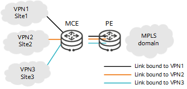
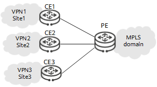
Increasingly refined user services and their growing demand for security require service isolation to be deployed on the network. On the network shown in Figure1 MCE networking, if traditional VPN architecture is used, one CE needs to be deployed for each VPN to connect to upper-layer devices. If these VPNs connect to upper-layer devices through the same CE, they will share the same routing and forwarding table. As a result, data security cannot be ensured.
MCE technology can effectively ensure data security on a network with multiple VPNs without increasing network costs.
MCE-related Concepts
To understand MCE, you need to understand the basic concepts of VPN and BGP/MPLS IP VPN, which are the basis for using MCE.
CE
Customer edges (CEs) are edge devices on the customer network. These devices directly connect to a service provider network through interfaces. CEs can be routers, switches, or hosts. Generally, CEs are unaware of VPNs and do not need to support MPLS.
PE
Provider edges (PEs) are edge devices on the service provider network. These devices directly connect to CEs. On an MPLS network, all VPN processing is performed on PEs. Therefore, the requirements for PE performance are high.
P
Provider devices (Ps) are backbone devices on the service provider network. These devices do not directly connect to CEs. Ps only need to have basic MPLS forwarding capabilities and do not need to maintain VPN information.
VPN
A VPN is a virtual private communication network established over the public network of an Internet service provider (ISP) or network service provider (NSP). VPNs have two basic features: dedicated and virtual. They can divide an existing IP network into logically isolated networks.
VPN Instance
A PE connects to CEs on different VPNs and receives routes from these CEs. Because the address spaces used by different VPNs may overlap, routes sent from different VPNs may carry the same destination address. If a PE has only one routing and forwarding table, routes with overlapping addresses will overwrite each other, causing route loss. To address this issue, VPN instances are introduced.
A PE has multiple routing and forwarding tables, including a public network routing and forwarding table and one or more VPN routing and forwarding tables. In other words, a PE has multiple instances, including one public network instance and one or more VPN instances. Each VPN instance maintains routes from the corresponding VPN, and the public network instance maintains public network routes. This prevents routes from getting lost on the PE due to destination address overlapping.
Site
A site is a group of IP systems with IP connectivity that can be achieved without the help of any ISP. Sites are divided based on the topology rather than the geographical locations of devices. A site can belong to multiple VPNs.
How Does MCE Work?
MCE Implementation Principles
A VPN instance is configured on the MCE device for each to-be-isolated service, and an independent routing protocol is deployed for each VPN to communicate with the MCE device. MCE extends the functions of PEs to CEs. MCE device interfaces and the peer PE interfaces are bound to the corresponding VPN instances. In addition, the MCE device creates and maintains an independent routing and forwarding table for each VPN. In this way, an independent channel is set up for each VPN user, achieving service isolation among these users.
As shown in the following figure, three VPN instances are configured on the MCE device: VPN1, VPN2, and VPN3. In this way, three independent VPN routing and forwarding tables are created on the MCE device. VPN1 is bound to the link between the MCE device and Site1, VPN2 is bound to the link between the MCE device and Site2, and VPN3 is bound to the link between the MCE device and Site3. Moreover, each of the three links between the MCE device and PE is bound to a different VPN instance. These configurations allow VPN services to be isolated using only one device.
After MCE is configured, the MCE device's VPN routing and forwarding tables contain routes to the corresponding LANs and remote sites for each service.

MCE networking
Route Exchange on an MCE Device
The MCE device learns routing information from VPN1 and stores the information in the routing and forwarding table for VPN1. The PE learns VPN1's routing information from the MCE device and stores the information. The routing information of VPN2 and VPN3 is not stored in the routing and forwarding table for VPN1. Therefore, VPN2 and VPN3 are isolated from VPN1.
Routing information is bound to VPN instances on the MCE device, and VPN instance packets are differentiated through interfaces between the MCE device and PE. The routing protocol running between the MCE device and PE can advertise VPN routing information so long as simple route configuration is performed on the MCE device and PE and VPN routing entries on the MCE device are imported into this protocol.
The MCE device and PE can use static routes, RIP, OSPF, IS-IS, or BGP to exchange routing information.
The MCE device can exchange routing information with a site in the following methods:
- Each VPN instance is bound to the corresponding static routes on the MCE device. The static routes of different VPNs are isolated even if these VPNs use overlapping address spaces.
- Each VPN instance is bound to a RIP process on the MCE device, so that routes of different VPNs can be exchanged between the MCE device and sites using different RIP processes. This ensures VPN route isolation and security.
- Each VPN instance is bound to an OSPF process on the MCE device to isolate the routes of different VPNs.
- Using IS-IS to advertise VPN routes between the MCE device and sites is similar to that using OSPF. Each VPN instance is bound to an IS-IS process.
- When BGP is used to advertise VPN routes between the MCE device and sites, a BGP peer needs to be configured for each VPN instance and the IGP routes of each VPN instance need to be imported into BGP on the MCE device.
What Are the Application Scenarios of MCE?
MCE Application on a Campus Network
On a campus network, BGP/MPLS IPv6 VPN can be used to isolate users. However, the number of users to be isolated is often limited in this situation. If PEs and Ps are still deployed, the deployment will be complex, driving up maintenance costs.
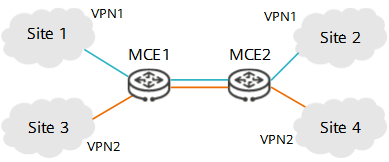
In this case, MCE can be used. As shown in the following figure, MCE is deployed on access-layer devices of the campus network, so that these devices function as MCE devices to connect to multiple VPNs and carry users' VPN routes. VPN routes can be directly transmitted to the peer MCE device for route exchange without the need of the carrier network.

MCE campus network
This networking offers the following benefits:
- Simplified configuration: MPLS and MP-BGP do not need to be configured.
- Reduced costs: PEs and Ps do not need to be deployed.
The method of deploying MCE on a campus network is as follows:
- MCE1 and MCE2 serve as CEs for each other. Bind the links between MCE1 and MCE2 to the corresponding VPNs and configure the same routing protocol on the two ends of each link.
- Bind the links between each MCE device and site to the corresponding VPNs and configure the same routing protocol on the two ends of each link.
If the routing protocol running between an MCE device and a site is different from that running between MCE devices, configure route import. The route type can be static route, RIPng, OSPFv3, IS-ISv6, or BGP4+. Determine which one to use according to the actual situation.
- Site2 sends a packet destined for Site1 to MCE2 based on the local routing and forwarding table.
- Upon receipt, MCE2 searches the corresponding VPN routing and forwarding table based on the inbound interface of the packet and forwards the packet to MCE1.
- Upon receipt, MCE1 searches the corresponding VPN routing and forwarding table based on the inbound interface of the packet and forwards the packet to Site1.
- Upon receipt, Site1 checks the destination address of the packet and processes this packet normally after finding that the destination address is itself.
Application of MCE on a Data Center Network
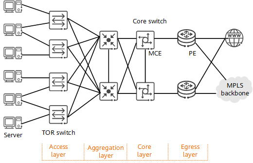
Data center network devices can be divided into four layers: egress layer, core layer, aggregation layer, and access layer. The egress layer forwards incoming and outgoing traffic of the data center at a high speed. The core layer forwards data traffic of different aggregation layers at a high speed. The aggregation layer provides functions such as gateway redundancy, load balancing, and firewall for servers. The access layer provides high-density network interfaces for data center servers.

MCE data center network
On a data center network, MCE is deployed on core switches to reduce the number of required CEs and simplify networking.
- Configure a different VPN instance for each service on core-layer devices.
- Bind each interface of a core-layer device to the corresponding VPN instance.
- Configure egress-layer devices (functioning as PEs) to connect to core-layer devices and bind interfaces used by egress-layer devices to connect to core-layer devices to the corresponding VPN instances.
- Deploy a routing protocol for egress-layer devices to communicate with core-layer devices.
- Author: Luo Haiyan
- Updated on: 2021-11-18
- Views: 6592
- Average rating:


