What Is MPLS?
Proposed by the Internet Engineering Task Force (IETF), MPLS is a protocol that uses labels to guide forwarding of data packets at a high speed over the IP backbone network. MPLS is a more efficient alternative to traditional IP routing and works by mapping an IP address to a short and fixed-length label of local significance, replacing IP table lookups with label swapping. In addition, MPLS labels can be used to establish a logical tunnel on the IP network. MPLS is compatible with different network-layer and link-layer protocols. Therefore, it can provide public network tunnels for various L2VPN, L3VPN, and EVPN services.
Why Do We Need MPLS?
In the mid-1990s, the volume of data transmitted across the Internet increased sharply with the rapid development of IP networks. Due to hardware limitations back then, IP technologies, using the longest match rule, had to use software for route lookups, resulting in low forwarding performance. This also restricted the development of IP networks. Against this backdrop, the IETF proposed the MPLS protocol to improve the forwarding performance of routing devices on IP networks.

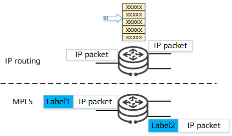
Comparison between IP routing and MPLS forwarding
Compared with traditional IP routing, MPLS improves forwarding performance in the following ways:
- It replaces time-consuming IP routing table lookups with simple label swapping, significantly reducing the time needed to guide packet forwarding.
- After a packet enters an MPLS domain, only the ingress and egress at the edge of the MPLS domain need to parse the IP packet header and encapsulate or decapsulate labels. The transit nodes only need to swap labels, further speeding up packet forwarding.
MPLS stopped providing notable improvements in forwarding performance of IP networks as application-specific integrated circuit (ASIC) technology developed and hardware took over as a fast way to process IP routing table lookups.
Nevertheless, MPLS found another purpose as its label-based forwarding is essentially a tunneling technology that can encapsulate multi-layer labels. In addition, MPLS works well with multiple network-layer and link-layer protocols, making it suitable for establishing public network tunnels in various VPN services. Finally, because MPLS packet forwarding depends on fixed label swapping paths, MPLS is a connection-oriented forwarding technology. This has resulted in its wide application across areas such as traffic engineering (TE) and QoS.
What Are the Characteristics of MPLS?
What Basic Concepts Are Involved in MPLS?
To understand what MPLS is, you need to first understand the concepts behind it. The following describes several core concepts.
FEC
MPLS is a class-based forwarding technology. It classifies data packets that may be forwarded the same way into one class, called forwarding equivalence class (FEC). MPLS processes data packets with the same FEC in the same way.
Packets can be classified into FECs based on any combination of the following elements: source address, destination address, source port, destination port, protocol type, service type, and so on. For example, all packets destined for the same destination address in IP routing using the longest match rule would be classified into the same FEC.
MPLS label
An MPLS label is a short, fixed-length identifier that has only local significance. It uniquely identifies the FEC to which a packet belongs. In some cases (for example, when load balancing is required), one FEC may be mapped to multiple MPLS labels. However, one label can represent only one FEC on one device.
An MPLS label has 4 bytes. The following figure shows how it is encapsulated.

Encapsulation structure of an MPLS label
An MPLS label has the following four fields:
Label: a 20-bit field that identifies a label value.
Exp: a 3-bit field used for extensions. Currently, this field is usually used for class of service (CoS).
BoS: a 1-bit field that identifies the bottom of a label stack. MPLS supports multiple labels, that is, label nesting. If the BoS field of a label is set to 1, the label is at the bottom of the label stack.
TTL: an 8-bit field indicating a time to live (TTL) value. This field is the same as the TTL field in IP packets.
An MPLS label is encapsulated between the link layer and network layer. The following figure shows where an MPLS label is encapsulated in a packet. MPLS labels are supported by all link-layer protocols.

Encapsulation position of an MPLS label
An MPLS label stack is also called an MPLS multi-layer label. It contains an ordered set of MPLS labels, as shown in the following figure. The label close to the Layer 2 header is known as the label "on top of the stack" or the outer label; the label close to the IP header is known as the label "at the bottom of the stack" or the inner label. The labels are processed from the top of the label stack in a last in first out manner.

MPLS label stack
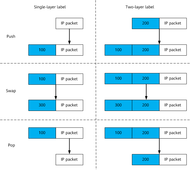
Label operations
The basic operations on MPLS labels include label push, label swap, and label pop. They are basic actions of label forwarding and a part of the label forwarding information base (LFIB).

Basic label operations
The basic operations on MPLS labels are as follows:
Push: When an IP packet enters an MPLS domain, the ingress adds a label between the Layer 2 header and the IP header of the packet. When the packet reaches a transit node, the transit node can also add a label to the top of the label stack (label nesting) as needed.
Swap: When the packet is forwarded inside the MPLS domain, a transit node searches the LFIB and replaces the label on top of the stack in the MPLS packet with the label that is assigned by the next hop.
Pop: When the packet leaves the MPLS domain, the egress removes the MPLS label; or the MPLS node at the penultimate hop removes the label on top of the stack to reduce the number of labels in the label stack.
Because MPLS labels are useless for the egress, you can configure penultimate hop popping (PHP) on the egress to allow the node at the penultimate hop to pop the label out of an MPLS packet so that the egress can directly forward the packet over IP or based on the inner label, thereby reducing the processing load on the egress.
PHP is implemented by allocating a special label value 3. A label with value 3 indicates an implicit-null label that never appears in a label stack. When the node at the penultimate hop finds that it is allocated with label value 3, it does not replace the label on top of the stack with this label. Instead, it pops the label so that the egress directly forwards the packet over IP or based on the inner label.
LSP
A label switched path (LSP) is a path along which packets that belong to the same FEC (that is, packets encapsulated with MPLS labels) are forwarded in an MPLS domain, as shown in the following figure.

LSP networking
An LSP is a unidirectional channel from the ingress to the egress. An LSP has the following roles:
Ingress: the start node of an LSP. An LSP has only one ingress. The ingress pushes an MPLS label into an IP packet and encapsulates the packet into an MPLS packet.
Transit node: an intermediate node on an LSP. An LSP may have any number of transit nodes, including zero. A transit node searches the LFIB and forwards MPLS packets through label swapping.
Egress: the last node of an LSP. An LSP has only one egress. The egress pops the label out of an MPLS packet and restores the original packet before forwarding it.
How Is an MPLS Network Structured?
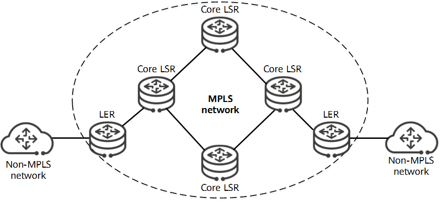
The following figure shows the typical structure of an MPLS network.

MPLS network structure
An MPLS network consists of the following elements:
- Label switching router (LSR): an MPLS-capable network device, which is fundamental to an MPLS network. A series of continuous LSRs constitutes an MPLS domain.
- Core LSR: resides in an MPLS domain and connects only to LSRs inside the domain.
- Label edge router (LER): resides on the edge of an MPLS domain and connects to one or more MPLS-incapable nodes.
On an MPLS network, an LSP can be set up between any two LERs to forward packets that enter an MPLS domain and can pass through one or more core LSRs. Therefore, the ingress and egress of an LSP are LERs, and transit nodes are core LSRs.
What Are the Benefits of MPLS?
MPLS is widely used on IP networks and provides the following benefits:
- MPLS is completely compatible with and is an improvement upon the IP network, making it easy to promote for its low construction costs.
- The control and forwarding planes of MPLS are separated. On the control plane, LSPs are set up based on IP routes. MPLS can borrow the flexibility and reliability mechanisms of IP routes where needed. On the connection-oriented forwarding plane, packets are transmitted over LSPs. In addition, MPLS can effectively implement TE and QoS.
- MPLS is independent of link-layer protocols. It supports protocols such as frame relay, ATM, PPP, and SDH, ensuring interworking of multiple types of networks and providing good compatibility.
- An MPLS network supports a hierarchical topology and is suitable for deployment on the IP backbone network.
- Theoretically, the MPLS label stack supports unlimited label nesting, which meets the requirements of VPN services for multi-layer encapsulation of public and private network labels. Therefore, MPLS provides strong support for the development of VPN services.
How Does MPLS Work?
Simply speaking, MPLS must correctly forward packets that enter an MPLS domain to their destination. This process is divided into two parts: LSP establishment and packet forwarding along the LSP.
How Does MPLS Establish LSPs?
MPLS is a technology that uses labels to guide packet forwarding. Therefore, the establishment of an LSP is a process in which LSRs along the LSP determine the labels for a specific FEC.
MPLS labels are assigned and distributed by a downstream LSR to an upstream LSR. As shown in the following figure, the downstream LSR classifies FECs based on the destination addresses of IP routes and allocates labels to the FECs corresponding to specified destination addresses. Then, the downstream LSR sends the labels to the upstream LSR, triggering the upstream LSR to establish an LFIB. Eventually, the series of LSRs form an LSP.

Process of establishing an LSP
LSPs can be classified into static LSPs and dynamic LSPs based on how they are established:
- Static LSPs are established by manually assigning labels to FECs. When manually assigning labels, the outgoing label value of the upstream LSR must be the same as the incoming label value of the downstream LSR.
- A dynamic LSP is set up when an LSR uses a label distribution protocol to dynamically generate and distribute labels. A downstream LSR uses IP routes to send labels to an upstream LSR. MPLS supports multiple label distribution protocols, such as the Label Distribution Protocol (LDP), Resource Reservation Protocol-Traffic Engineering (RSVP-TE), and Multiprotocol Extensions for Border Gateway Protocol (MP-BGP).
How Are Packets Forwarded Along LSPs?
Take a PHP-capable LSP as an example. MPLS packets are forwarded along the LSP as follows:
After receiving an IP packet destined for 192.168.1.1/24, the ingress pushes label Y into the packet, encapsulates the packet into an MPLS one, and forwards it.
Upon receipt, the first transit node swaps label Y with label X.
The transit node at the penultimate hop receives the MPLS packet and pops label X because the label value assigned by the egress is 3. The transit node then forwards the IP packet to the egress.
After receiving the IP packet, the egress forwards it to the destination address 192.168.1.1/24.

Packet forwarding through an LSP
What Is an MPLS VPN?
MPLS VPN is a technology that uses MPLS to construct VPNs on an IP backbone network. The essence of VPN is to transmit service data across a public network as if it was on a private network. This requires a tunnel to be set up on the public network so that data packets can be transmitted directly to the destination through the tunnel. Generally, MPLS VPN uses LSPs established using MPLS as public network tunnels to transmit private network service data.
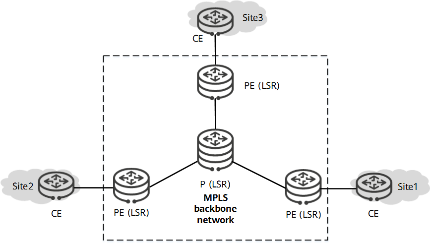
The basic MPLS VPN model consists of the following roles:
Customer edge (CE): an edge device on a user network. A CE is directly connected to a service provider (SP) network through interfaces. The VPN sites of users are connected to the SP network through the CE. A CE can be a network device or a host. Generally, CEs are unaware of VPNs and do not need to support MPLS.
Provider edge (PE): an edge device on an SP network. A PE is directly connected to a CE. On an MPLS network, PEs function as LSRs and process all MPLS and VPN services. This places high requirements on the performance of PEs.
Provider (P): a backbone device on an SP network. A P is not directly connected to a CE. On an MPLS network, a P functions as an LSR and only needs to process MPLS services. It does not need to maintain VPN information.

Basic MPLS VPN model
MPLS VPN fully leverages the technical advantages of MPLS and is the most widely used VPN technology. MPLS VPN offers the following benefits to users:
- An MPLS label corresponds to the data flow of a specified service (specific FEC), which helps to isolate services of different users.
- MPLS provides TE and QoS capabilities. Users can use MPLS to fully optimize VPN resource configuration.
- In addition, MPLS VPN provides flexible policy control to meet the special requirements of different users and implement value-added services quickly.
- Author: Guo Fenghai
- Updated on: 2021-09-30
- Views: 19863
- Average rating:


