What Is SR-MPLS?
SR-MPLS forwards data packets using the source routing model. The core idea of SR-MPLS is to divide a packet forwarding path into different segments, allocate segment identifiers (SIDs) to the segments, and encapsulate segment information into packets at the ingress of the path to guide packet forwarding.
Why Do We Need SR-MPLS?
Global digitalization is accelerating the development of the Internet. At the same time, the emergence of new requirements and services brings new opportunities and challenges to the Internet. Against this backdrop, how can service providers adjust the network architecture to adapt to the various service types? And how can they provide higher bandwidth and service quality as the network scale expands and the network structure becomes more and more complex? Aiming at simplifying networks, SR is designed to help service providers complete service-driven network transformation through protocol simplification.
Challenges Facing Traditional MPLS Technologies
Multi-Protocol Label Switching (MPLS) is a data forwarding technology that works between Layer 2 and Layer 3. Although the MPLS forwarding plane is praised thanks to MPLS's label switching concept, the MPLS control plane is criticized due to defects such as complex protocols, poor extensibility, and difficult deployment/maintenance. As the two major protocols used in the MPLS control plane, Label Distribution Protocol (LDP) and Resource Reservation Protocol-Traffic Engineering (RSVP-TE) have some disadvantages.
LDP, which distributes labels based on IGP path computation results, mainly has the following disadvantages:
- Because LDP depends on IGP but both protocols are independent of each other, LDP-IGP asynchronization exists, resulting in traffic blackholing.
- LDP can forward traffic only through the shortest path and does not support either traffic engineering or path planning.
Although RSVP-TE implements traffic engineering and therefore supports flexible selection of forwarding paths based on service requirements, it also has the following significant disadvantages:
- In addition to complex configuration and maintenance, RSVP-TE involves complex protocol states and requires devices to exchange many packets to maintain tunnel states, making large-scale deployment difficult.
- RSVP-TE does not support load balancing, lowering network resource utilization.
SR-MPLS aims to overcome the issues associated with traditional MPLS networks while also retaining the advantages of such networks.
Impacts of SDN
Traditional network architectures inherently involve tightly coupled and interdependent device hardware, operating systems (OSs), and network applications. To solve these issues, Professor Nick McKeown's team at Stanford University proposed a new network architecture — SDN — by drawing on the universal hardware, software-defined functions, and open-source model in the computer field.
SDN has three major characteristics: network openness and programmability, logical centralized control, and separation between control and forwarding planes. Any network with these three characteristics can be called an SDN network. An early example of SDN is OpenFlow, which is a protocol used for the communication between SDN control and forwarding planes. OpenFlow requires all network hardware to be upgraded or replaced, revolutionizing traditional networks and changing the network architecture from a distributed one to a centralized one. However, this revolutionary concept is too ideal to be implemented as expected. In contrast, SR supports both traditional and SDN networks and is compatible with existing devices, ensuring smooth evolution to SDN networks.

Network architecture evolution
Technical Value of SR-MPLS
SR-MPLS has emerged along with the SDN trend. It simplifies networks and offers excellent extensibility, reflected mainly in the following aspects:
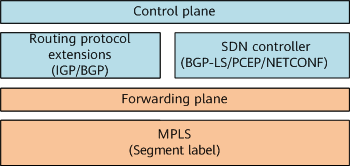
- Simpler control plane: Deploying LDP/RSVP-TE is not required. Instead, devices need to use only IGP/BGP extensions for label distribution and synchronization. Alternatively, a controller is used to uniformly distribute SR labels and deliver or synchronize them to devices.
- Easy-to-extend forwarding plane: SR-MPLS reuses the existing MPLS forwarding plane, enabling network devices to support SR forwarding through simple upgrades or even without any modification. In SR-MPLS, segments can be mapped to MPLS labels, and paths can be considered as label stacks.
SR-MPLS control and forwarding planes
Thanks to its simplicity, high efficiency, and excellent extensibility, SR-MPLS offers the following benefits:
- Supports network path programming. Leveraging the advantage of the source routing mechanism, SR-MPLS enables the ingress to control a service path by merely performing label operations on packets. In addition, transit nodes do not need to maintain path information, reducing the pressure on the control plane.
- Simplifies the device control plane, reduces the number of required routing protocols, and lowers O&M costs. In addition, the label forwarding table is simple and does not contain a large number of labels, reducing the device resource usage.
- Enables smoother evolution to SDN networks. As an SDN-oriented protocol, SR-MPLS integrates the advantages of both independent forwarding and centralized programming control to better implement application-driven networks. Furthermore, it supports both traditional and SDN networks and is compatible with existing devices, ensuring smooth evolution to SDN networks.
SR-MPLS vs. MPLS
SR-MPLS retains the advantages of the MPLS forwarding plane, enabling SR-MPLS to be directly applied to the existing MPLS architecture. In addition, SR-MPLS revolutionizes traditional MPLS technologies. The following figure shows the major advantages of SR-MPLS by comparing it with MPLS.
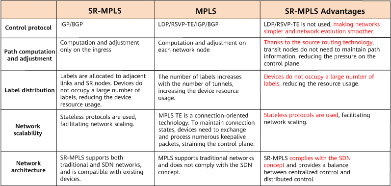
Comparison between SR-MPLS and MPLS
How Does SR-MPLS Work?
SR-MPLS divides the packet forwarding path into different segments, allocates SIDs to the segments, and inserts segment information into packets on the ingress of the path to guide packet forwarding to the destination. Focusing on SID allocation and propagation, the following describes how LSPs are established in the control plane and how data packets are forwarded in the forwarding plane.
Before learning how SR-MPLS works, let's see the basic concepts of SR-MPLS.
Basic Concepts of SR-MPLS
What Is a Segment?
A segment represents a network instruction dictating where packets should go and how they should get there. Segments are classified as prefix, node, or adjacency segments, depending on the generation mode.

Segment classification
What Is a SID?
A SID uniquely identifies a segment in the SR domain and can be mapped to an MPLS label in the forwarding plane. SIDs are also classified as prefix, node, or adjacency SIDs, as shown in the preceding figure.
- A prefix SID (also called a prefix label) is a label mapped to a destination IP address.
- A node SID (also called a node label) is a label mapped to the IP address of a loopback interface on a device. It can be considered as a special prefix SID.
- An adjacency SID (also called an adjacency label) is advertised by a device to its interface neighbor in order to explicitly specify a link for packet forwarding in the designated direction. For example, the adjacency SID 16024 allocated by P2 indicates that packets need to be sent to P4 through the local interface Interface1.
The prefix/node SIDs and adjacency SIDs are equivalent to destination addresses and outbound interfaces, respectively, in traditional IP forwarding.
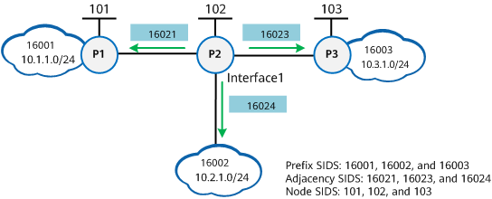
Prefix, node, and adjacency SIDs
What Is a Segment List?
A segment list is an ordered list of segments used to represent a packet forwarding path. It can be considered as an MPLS label stack in the forwarding plane.
What Is an SRGB?
An SRGB is a set of user-defined global labels reserved for SR-MPLS. It needs to be manually configured. Labels in the set can be allocated only to prefix and node SIDs, and adjacency SIDs are local SIDs out of the SRGB range.
How Are SR-MPLS LSPs and SR-MPLS TE Tunnels Established?
SR-MPLS LSPs are essentially label forwarding paths established using the SR technology. As such, SR-MPLS LSP establishment is a process in which prefix and node SIDs are allocated and propagated, whereas SR-MPLS TE tunnel establishment is a process in which adjacency SIDs are allocated and propagated.
Node SID Allocation and Propagation
Assume that P4 in the following figure is the destination node on which a node SID is manually configured. After P4 propagates the node SID to the other nodes in the IGP domain through an IGP, all these nodes learn the SID. They then run the shortest path first (SPF) algorithm to compute a label forwarding path to P4 and generate corresponding forwarding entries.
Paths represented by node SIDs are SR-MPLS BE LSPs (the optimal SR LSPs computed by the IGP using the SPF algorithm).

Node SID allocation and propagation
Prefix SID Allocation and Propagation
Assume that P4 in the following figure is the destination node on which a prefix SID is manually configured. After P4 propagates the prefix SID to the other nodes through an IGP, these nodes parse the SID and calculate label values according to their own SRGBs. Then, based on the IGP-collected topology information, each of these nodes runs the SPF algorithm to compute a label forwarding path, and delivers the computed next hop and OuterLabel information to the forwarding table to guide data packet forwarding.
Paths represented by prefix SIDs are also SR-MPLS BE LSPs.
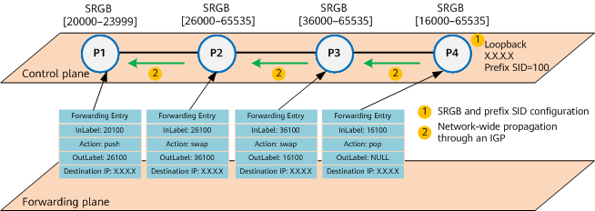
Prefix SID allocation and propagation
The process of establishing an LSP based on a prefix SID is as follows:
- After an SRGB is configured on P4 and a prefix SID is configured for the specified loopback interface of P4, P4 generates the corresponding forwarding entry and delivers it. P4 then encapsulates the SRGB and prefix SID into an LSP packet and floods the packet to the entire network through an IGP.
After receiving the LSP packet, other nodes on the network parse the prefix SID advertised by P4, and also calculate label values according to their own SRGBs as well as OuterLabel values according to the SRGBs advertised by the next hops. Using the IGP-collected topology information, they compute label forwarding paths and generate forwarding entries accordingly.
- P3 parses the prefix SID advertised by P4 and calculates a label value according to its own SRGB [36000–65535] through the following formula: Label = Start value of the SRGB + Prefix SID value. In this example, the start value of the SRGB is 36000, and the prefix SID value is 100. Therefore, the label value is 36100 (36000 + 100).
Based on IS-IS topology information, P3 calculates the OuterLabel value through the following formula: OuterLabel = Start value of the SRGB advertised by the next hop + Prefix SID value. In this example, the next hop is P4, which advertises the SRGB [16000–65535]. Therefore, the OuterLabel value is 16100 (16000 + 100).
- The calculation process on P2 is similar to that on P3. In this example, the label value is 26100 (26000 + 100), and the OuterLabel value is 36100 (36000 + 100).
- The calculation process on P1 is also similar to that on P3. In this example, the label value is 20100 (20000 + 100), and the OuterLabel value is 26100 (26000 + 100).
Adjacency SID Allocation and Propagation
As shown in the following figure, P2 allocates an adjacency SID to each neighbor. Adjacency SIDs are automatically generated by an IGP for neighbors by default, and they can also be manually configured. Adjacency SIDs are also propagated to other nodes through the IGP. However, forwarding entries are generated only on the nodes to which adjacency SIDs are allocated. In this example, a forwarding entry is generated only on P2.
A segment list that contains multiple adjacency SIDs can be defined on the ingress to implement refined path planning. Therefore, paths represented by adjacency SIDs are called SR-MPLS TE tunnels, which can be used to better implement traffic engineering.
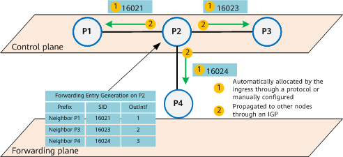
Adjacency SID allocation and propagation
The functions of prefix, node, and adjacency SIDs are as follows:
- Prefix and node SIDs can both identify a node. From the perspective of the forwarding plane, such SIDs guide packet forwarding to this node along the shortest path that supports equal-cost multi-path (ECMP). Therefore, the forwarding path established based on a prefix or node SID is not fixed, and the ingress cannot control the entire forwarding path. As such, forwarding paths established based on prefix or node SIDs are called SR-MPLS BE LSPs.
- Adjacency SIDs are locally allocated to interface neighbors. From the perspective of the forwarding plane, such SIDs guide packet forwarding through the specified outbound interface or next hop. Any explicit path can be strictly specified by defining a segment list with one or more adjacency SIDs on the ingress. As such, forwarding paths established based on adjacency SIDs are called SR-MPLS TE tunnels. This establishment mode facilitates SDN implementation. In addition, strictly specified explicit paths are also called strict paths, which are a type of SR-MPLS TE tunnel.
Prefix, node, and adjacency SIDs can either be used separately or be combined. As shown in the following figure, a forwarding path can be established based on a combination of adjacency and node SIDs. The adjacency SID can be used to force a path to traverse an adjacency. Based on the node SID, nodes can run the SPF algorithm to compute the shortest path or compute multiple paths to load-balance traffic. Because the forwarding path established in this mode is not fixed, it is also called a loose path, which is another type of SR-MPLS TE tunnel.
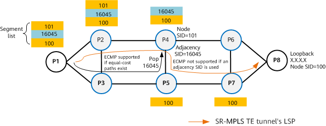
Adjacency SID + node SID-based forwarding path
How Are Packets Forwarded?
After learning SR-MPLS BE LSPs and SR-MPLS TE tunnels (consisting of strict and loose paths), which are established based on different types of SIDs, let's see how packets are forwarded over them.
Prefix SID-based Data Packet Forwarding
Take a prefix SID-based SR-MPLS BE LSP as an example. The process of packet forwarding over the LSP is as follows:
- After receiving a data packet, P1 adds label 26100 to the packet and then forwards the packet.
- After receiving the labeled packet, P2 swaps label 26100 with label 36100 and then forwards the packet.
- After receiving the labeled packet, P3 swaps label 36100 with label 16100 and then forwards the packet.
- After receiving the labeled packet, P4 removes label 16100 and searches the routing table for further packet forwarding.
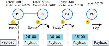
Prefix SID-based data forwarding
Adjacency SID-based Data Packet Forwarding
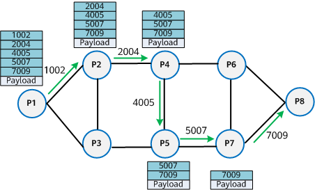
After a segment list with multiple adjacency SIDs is defined on the ingress, packets are forwarded along the strictly specified explicit path (SR-MPLS TE tunnel's LSP) through the forwarding process:
- After receiving the data packet, P1 adds the label stack <1002, 2004, 4005, 5007, 7009> to the packet, searches for the adjacency matching the top label 1002, finds that the corresponding outbound interface is on the P1->P2 adjacency, and then removes label 1002. In this case, the packet carrying the label stack <2004, 4005, 5007, 7009> is forwarded to the downstream node P2 through the P1->P2 adjacency.
- After receiving the packet, P2 searches for an adjacency matching the top label 2004, finds that the corresponding outbound interface is on the P2->P4 adjacency, and then removes the label 2004. In this case, the packet carrying the label stack <4005, 5007, 7009> is forwarded to the downstream node P4 through the P2->P4 adjacency.
- After receiving the packet, P4, P5, and P7 process the packet in the same way as P2. After removing the last label 7009, P7 forwards the packet to P9.
- Because the packet received by P9 does not contain any label, P9 searches the routing table for further packet forwarding.
Adjacency SID-based data forwarding
Adjacency SID + Node SID-based Data Packet Forwarding
If strict path-based SR-MPLS TE is used in a scenario where equal-cost paths exist, load balancing cannot be implemented. To address this issue, node SIDs are introduced to SR-MPLS TE paths.
After a label stack that consists of both node and adjacency SIDs is manually specified on the ingress, forwarders can search for outbound interfaces hop by hop based on the stack and remove labels to guide packet forwarding to the destination. The packet forwarding process is as follows:
- According to the top adjacency label 1003, P1 finds that the corresponding outbound interface is on the P1->P3 adjacency. It then removes the label 1003 and forwards the packet to the next-hop node P3.
- Similar to P1, P3 searches for the corresponding outbound interface according to the top label 1006, removes the label, and then forwards the packet to the next-hop node P2.
- Similar to P1, P2 searches for the corresponding outbound interface according to the top label 1005, removes the label, and then forwards the packet to the next-hop node P4.
- P4 processes the top node label 101. Because load balancing for the traffic to P7 is supported in this case, the traffic is hashed to corresponding links based on IP 5-tuple information.
- P5 and P6 perform operations according to the node label 101 and swap the label with the next-hop node label. Because the two nodes are penultimate hops, they remove the label and forward the packet to P7 to complete E2E traffic forwarding.
According to the preceding process, manually specifying both node and adjacency labels enables devices to forward traffic in either shortest-path or load-balancing mode. Because the forwarding paths are not fixed, this forwarding mode is called loose path-based SR-MPLS TE.
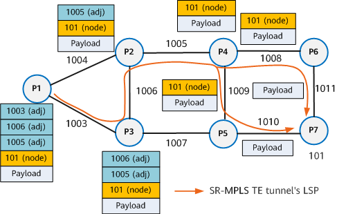
Adjacency SID + node SID-based data packet forwarding
From SR-MPLS to SRv6
Due to its low complexity, high efficiency, and excellent extensibility, SR-MPLS has been widely accepted by the industry since its birth. Although MPLS forwarding plane-based SR-MPLS can provide a high degree of programmability, it cannot meet the requirements of services that need to carry data through extension headers due to the poor extensibility of MPLS encapsulation. IPv6 forwarding plane-based SRv6 not only inherits all the advantages of SR-MPLS, but also provides greater extensibility.
SR-MPLS is implemented based on the MPLS forwarding plane and uses MPLS labels to identify SIDs. However, Segment Routing IPv6 (SRv6) — which is implemented based on the IPv6 forwarding plane — does not involve MPLS labels. So if MPLS labels are not used, how does SRv6 identify SIDs? To answer this question, let's first see the differences between SRv6 and SR-MPLS in terms of the frame structure.

SR-MPLS

SRv6
From the preceding figure, we can see that SRv6 inserts an SRH into IPv6 packets to replace traditional MPLS's label forwarding function. The SRH stores IPv6 segment list information and functions the same as a segment list in SR-MPLS.
For details about SRv6, see What Is SRv6.
- Author: Liu Yan
- Updated on: 2021-12-06
- Views: 21252
- Average rating:


