Search
Home Search Center IP Encyclopedia Online Courses Intelligent Model Selection

What Is PFC?

The meaning of PFC is Priority-based Flow Control. It is the most widely used flow control technology that can effectively prevent packet loss and serve as the basis for intelligent lossless networks. A PFC-enabled queue is a lossless queue. When congestion occurs in such a queue on a downstream device, the downstream device instructs the upstream device to stop sending traffic in the queue, implementing zero packet loss.

Why Do We Need PFC?

Disadvantages of Traditional Flow Control Technologies

The most fundamental flow control technology is the Ethernet Pause mechanism defined in IEEE 802.3. When a downstream device detects that its receive capability is lower than the transmit capability of its upstream device, it sends Pause frames to the upstream device, requesting the upstream device to stop sending traffic for a period of time.
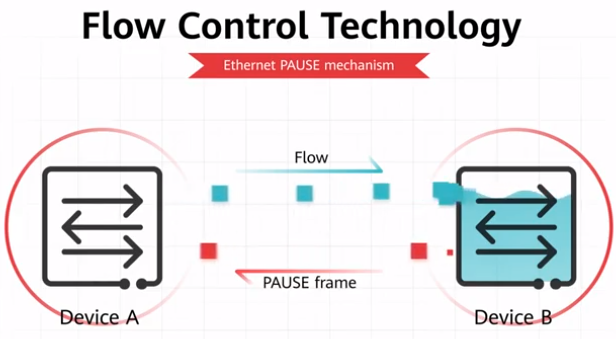
Implementation of the Ethernet Pause mechanism
The drawback, however, is that the Ethernet Pause mechanism stops all traffic on a link (for the entire interface). This in turn affects link sharing, which is critical to actual services. Link sharing requires:
  • Burst traffic of one type cannot affect forwarding of other types of traffic.
  • A large amount of one type of traffic in a queue cannot occupy buffer resources of other types of traffic.
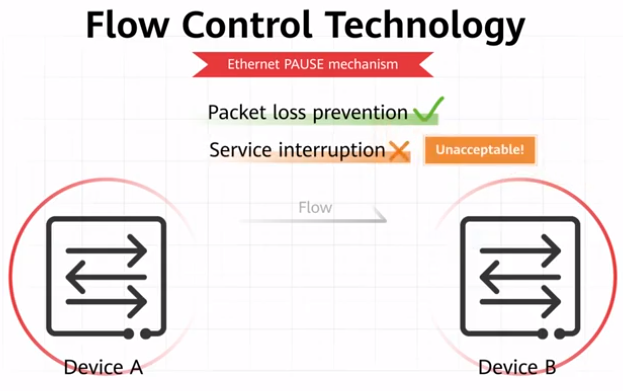
Disadvantages of the Ethernet Pause mechanism

How Does PFC Work?

PFC enhances Ethernet Pause. As shown in the figure, eight priority queues on the transmit interface of DeviceA correspond to eight receive buffers on the receive interface of DeviceB. When a receive buffer on DeviceB is congested, DeviceB sends a backpressure signal "STOP" to DeviceA, requesting DeviceA to stop sending traffic in the corresponding priority queue.

PFC addresses the conflict between the Ethernet Pause mechanisms and link sharing. It controls traffic only in one or several priority queues of an interface, rather than on the entire interface. What's more, PFC can pause or restart any queue, without interrupting traffic in other queues. This feature enables traffic of various types to share one link.
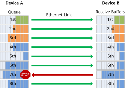
PFC working mechanism

What Is rPFC?

Remote PFC (rPFC) is a technology that restricts PFC to the network edge to stop PFC frames from spreading, thereby preventing network performance deterioration caused by local congested nodes.

PFC is a flow control technology that effectively prevents packet loss. However, when a server or the destination switch at the network edge sends PFC frames to the network upon congestion, the PFC frames spread across the network, impacting overall network performance. rPFC, however, can accurately locate the source switch of a congested flow when it is detected on the destination switch, and then remotely instruct the source switch to perform precise flow control. This prevents PFC frames from spreading across the network and ensures stable network performance.

Impact of PFC on the network

On a PFC-enabled network shown in preceding figure, when the destination switch at the network edge is congested and the queue buffer reaches the threshold for triggering PFC frames, the destination switch sends PFC frames to the corresponding priority queue on the upstream device. The PFC frames then spread to the spine and leaf nodes on the network until the source switch that sends the congested flow at the network edge receives the PFC frames. The source switch then performs PFC on the source server, and the source server stops sending traffic to the priority queue. Throughout this process, PFC frames are spread from the local congested node at the network edge to the entire network, affecting the network performance.

Implementation of the rPFC function

As shown in the preceding figure, after rPFC is enabled on leaf nodes, when detecting a congested flow, the destination switch sends an rPFC notification packet to the source switch of the congested flow. When receiving the rPFC notification packet, the source switch performs PFC on the source server, which then stops sending traffic to the priority queue. Throughout this process, PFC is restricted to the network edge to prevent PFC frames from spreading and ensure stable network performance. rPFC is implemented as follows:

  1. Destination switch:
    1. Congested flow detection: obtains congested flow information using the latency visualization function of Packet Event.
    2. Congestion notification: sends an rPFC notification packet to the source switch of the congested flow. However, if the source switch is also the destination switch, no subsequent rPFC operations are performed.
  2. Source switch:
    1. Notification receipt: receives an rPFC notification packet from the destination switch.
    2. Flow control: decapsulates the rPFC notification packet, obtains the PFC frame, and sends the PFC frame to the source server.
About This Topic
  • Author: Ma Shuai
  • Updated on: 2025-04-10
  • Views: 25964
  • Average rating:
Share link to