What Is Virtual Local Area Network (VLAN)
Virtual Local Area Network (VLAN) technology logically divides a physical LAN into multiple broadcast domains, each of which is called a VLAN.
Each VLAN functions as a separate broadcast domain, with devices in the same VLAN able to directly communicate with one another, while those in different VLANs cannot. As a result, broadcast packets are confined within a single VLAN.
Why Do We Need VLAN?
Early Ethernet allows data communication over shared media through Carrier Sense Multiple Access/Collision Detection (CSMA/CD). When an Ethernet network has a large number of hosts, collision becomes a serious problem and can lead to broadcast storms. This degrades network performance or even causes a complete breakdown. Using Layer 2 devices to connect LANs can restrict data transmission within a LAN. However, this resolves only the conflicts.
This is where VLAN technology comes in. VLAN technology allows a physical LAN to be divided into multiple logical LANs (multiple VLANs). Each VLAN functions as a separate broadcast domain, with hosts in the same VLAN able to directly communicate with one another, while those in different VLANs cannot. As a result, broadcast packets are confined within a single VLAN. The following figure shows an example.
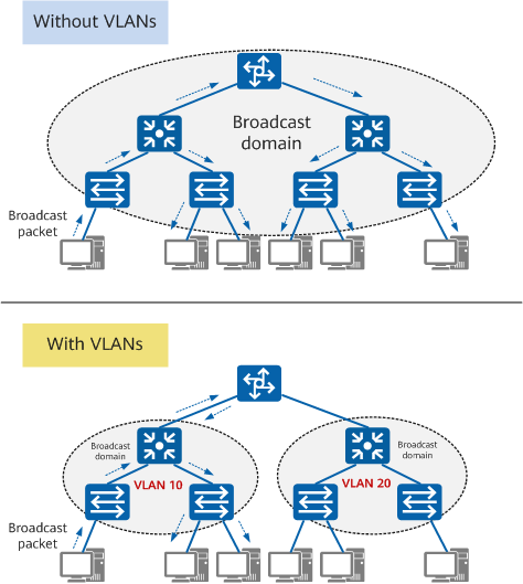
Functions of a VLAN
- Confines each broadcast domain to a single VLAN. This conserves bandwidth and improves network processing capabilities.
- Enhances LAN security. Frames in different VLANs are separately transmitted, so that hosts in a VLAN cannot directly communicate with those in another VLAN.
- Improves network robustness. A fault in one VLAN does not affect hosts in another VLAN.
- Allows for flexible virtual groups. VLAN technology allows hosts in different geographical locations to be added to different groups, simplifying network construction and maintenance.
VLAN vs Subnet
A network can be divided into multiple subnets to conserve IP address space and support flexible IP addressing.
Similar to a VLAN, a subnet can also isolate hosts. Hosts in different subnets cannot communicate with each other. The following figure shows the comparison between VLANs and subnets.
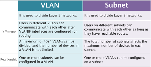
VLAN vs subnet
VLAN Tag and VLAN ID
IEEE 802.1Q adds a 4-byte VLAN tag to an Ethernet frame, enabling switches to identify the VLAN to which the received frame belongs.
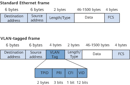
VLAN-tagged frame format defined in IEEE 802.1Q
The VID field in a data frame identifies the VLAN to which the frame belongs (that is, the VLAN ID). The frame can only be transmitted within this VLAN. This field ranges from 0 to 4095. The values 0 and 4095 are reserved, and therefore available VLAN IDs are in the range from 1 to 4094.
All frames processed in a switch carry VLAN tags, but some devices, such as hosts and servers, connected to a switch cannot process VLAN-tagged frames. To enable communication between the switch and these devices, the switch interfaces must be able to identify whether an Ethernet frame is tagged, and add VLAN tags to or remove VLAN tags from the frames when sending and receiving these frames. When the switch receives an untagged frame, it adds a VLAN tag to the frame according to the default VLAN, that is, Port Default VLAN ID (PVID) of the interface that received the frame.
Interface Types and VLAN Tag Processing
Hosts in the same VLAN may be connected to different switches, and a VLAN can span multiple switches. To enable communication between hosts, interfaces between switches must be able to identify and send VLAN-tagged frames of multiple VLANs. Ethernet interfaces of different types can be configured to satisfy different networking requirements, depending on the objects connected to them and the way they process frames.
Different vendors may define different VLAN interface types. On Huawei devices, Ethernet interfaces are classified into access, trunk, and hybrid interfaces.
Access Interface
An access interface often connects to a terminal (such as a PC or server) that cannot or does not need to identify VLAN tags.
- Untagged frame: an original frame without a 4-byte VLAN tag
- Tagged frame: a frame with a 4-byte VLAN tag
In most cases, access interfaces accept and send only untagged frames, and tag frames that do not carry a VLAN tag with its Port Default VLAN ID (PVID). Since only tagged frames can be processed in a switch, the default VLANs for access interfaces must be set. After the default VLAN is configured for an access interface, the access interface joins this VLAN and adds the corresponding VLAN tag to received untagged frames.
An access interface accepts VLAN-tagged frames only when they are tagged with a VLAN ID that matches its PVID.
An access interface removes the VLAN tag from a tagged frame before sending the frame out.
Trunk Interface
A trunk interface often connects to a switch, router, AP, or voice terminal that can accept and send both tagged and untagged frames. It accepts VLAN-tagged frames of multiple VLANs and only sends frames in the default VLAN as untagged.
The default VLAN of a trunk interface is defined as the native VLAN by some vendors. When a trunk interface receives an untagged frame, it adds the native VLAN tag to the frame.
Hybrid Interface
A hybrid interface can connect to a user terminal (such as a host or server) or network device (such as a hub) that cannot identify VLAN tags, and also can connect to a switch, a router, an AP, or a voice terminal that can accept and send tagged and untagged frames. It accepts VLAN-tagged frames of multiple VLANs. Depending on your configuration, frames sent out from a hybrid interface may be tagged or untagged.
Hybrid and trunk interfaces can be interchanged in some scenarios, but hybrid interfaces must be used in specified scenarios, for example, selective QinQ. Before frames from multiple VLANs provided by a service provider enter a user network, the outer VLAN tags must be removed. Trunk interfaces cannot be used here because they allow only frames from their default VLANs to pass through as untagged.
VLAN Application Scenarios
Users can be isolated at Layer 2 using VLANs and can communicate with each other at Layer 3 through VLANIF interfaces.
Inter-VLAN Layer 2 Isolation
In the following figure, there are multiple companies in a building. These companies share network resources to reduce costs. Networks of the companies connect to different interfaces of the same Layer 2 switch and access the Internet through the same egress router.
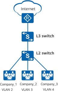
Networking diagram of interface-based VLAN assignment
To isolate the services of different companies and ensure service security, assign interfaces connected to the company networks to different VLANs. In this way, each company has a virtual router, and each VLAN works as a virtual work group.
In the following figure, a company has two departments assigned with fixed IP network segments. The employees often move between locations, but the company requires that their network resource access rights remain unchanged.
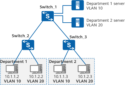
Networking diagram of subnet-based VLAN assignment
To ensure that employees retain access to network resources after changing locations, assign VLANs based on subnets on Switch_1. In this case, servers on different subnets are assigned to different VLANs to isolate data flows for accessing application services on the servers, improving security.
Inter-VLAN Layer 3 Communication
In the following figure, departments 1 and 2 of a small-scale company belong to VLAN 2 and VLAN 3, respectively, and connect to a Layer 3 switch (Switch_3) through Layer 2 switches. Packets exchanged between the two departments need to pass through the Layer 3 switch.
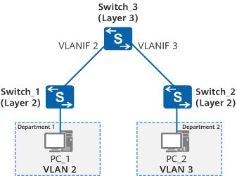
Inter-VLAN Layer 3 communication through VLANIF interfaces
Assign VLANs on Switch_1 and Switch_2, configure Switch_1 and Switch_2 to transparently transmit VLAN frames to Switch_3, and configure a VLANIF interface for each VLAN on Switch_3 to allow communication between VLAN 2 and VLAN 3.
VLAN-related Protocols
IEEE 802.1Q
IEEE 802.1Q, often referred to as Dot1q, defines the VLAN implementation standard for Virtual Bridged Local Area Networks. Compared with a standard Ethernet frame, a VLAN-tagged frame has an extra 4-byte VLAN tag.
LNP
- When the link type on an Ethernet interface is negotiated as access, the interface joins VLAN 1 by default.
- When the link type on an Ethernet interface is negotiated as trunk, the interface joins VLANs 1 to 4094 by default.
QinQ
The 802.1Q-in-802.1Q (QinQ) protocol is known as an amendment to the IEEE 802.1ad protocol. It expands VLAN space by adding an additional 802.1Q tag to 802.1Q-tagged packets, and allows packets in a private VLAN to be transparently transmitted over a public network.
A packet transmitted on the backbone network carries two 802.1Q tags: a public VLAN tag and a private VLAN tag.
What Are Disadvantages of VLAN in Cloud-based Scenarios
Cloud computing, relying on its high system utilization rate, low manpower and management costs, and flexible and expandable performance advantages, has already become the current new form of enterprise IT construction. As a core technology of cloud computing, server virtualization has a wide range of applications.
VLAN is a traditional network isolation technology. In accordance with standards, a maximum of about 4096 VLANs are available, which cannot meet the tenant isolation requirements of large data centers. In addition, each VLAN is a small and fixed Layer 2 domain, and as such is not suitable for large-scale dynamic virtual machine (VM) migration.
To solve this problem, Virtual eXtensible Local Area Network (VXLAN) was introduced. Defined in RFC, VXLAN is a Network Virtualization over Layer 3 (NVO3) technology that uses MAC-in-User Datagram Protocol (MAC-in-UDP) encapsulation. VXLAN overcomes the preceding disadvantages of VLAN. VXLAN uses the 24-bit VXLAN Network Identifier (VNI) field to identify up to 16 million tenants, compared to a maximum of 4096 tenants in VLAN. VXLAN establishes a virtual tunnel between two switches across the basic IP network of the data center and virtualizes the data center network into a large Layer 2 virtual switch to meet the requirements of large-scale dynamic VM migration.
- Author: Zhu Yue
- Updated on: 2021-11-24
- Views: 23537
- Average rating:


