What Is VXLAN?
VXLAN, or Virtual Extensible LAN, is a network virtualization technology widely used on large Layer 2 networks. VXLAN establishes a logical tunnel between the source and destination network devices, through which it uses MAC-in-UDP encapsulation for packets. Specifically, it encapsulates original Ethernet frames sent by a VM into UDP packets. It then encapsulates the UDP packets with the IP header and Ethernet header of the physical network as outer headers, enabling these packets to be routed across the network like common IP packets. This frees VMs on the Layer 2 network from the structural limitations of the Layer 2 and Layer 3 networks.
Why Do We Need VXLAN?
Why do we need VXLAN? Under the trend of server virtualization, dynamic VM migration occurs, which requires IP addresses and MAC addresses to remain unchanged before and after migration. Server virtualization also leads to a sharp increase in the number of tenants, which the network needs to effectively isolate.
Dynamic VM Migration
Traditional server virtualization works by virtualizing a physical server into multiple logical servers known as VMs. Server virtualization is an effective way of improving server efficiency while reducing energy consumption and operational costs. Such advantages account for its wide use.
Since server virtualization was widely adopted, dynamic VM migration has become increasingly common. To ensure service continuity during the migration of a VM, the VM's IP address and running status (for example, the TCP session status) must remain unchanged. Therefore, VMs can only be dynamically migrated in the same Layer 2 domain.
As shown in the following figure, the traditional three-layer network architecture limits the dynamic VM migration scope. VMs can only migrate within a limited scope, greatly restricting application.
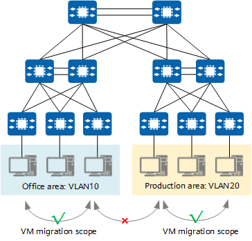
Traditional three-layer network architecture limiting the dynamic VM migration scope
To enable smooth VM migration over a large scope or even between regions, all involved servers must be deployed in a large Layer 2 domain.
A Layer 2 switch can support Layer 2 communication between servers connected to the switch. When a server is migrated from one port of the Layer 2 switch to another port, the IP address of the server can remain unchanged. This meets the requirements for dynamic VM migration. It is this concept that inspired the design of VXLAN.
VXLAN provides a methodology for creating a virtual tunnel on the IP network to transparently forward user data when communication is required between a source and destination node on the IP network. Any two nodes can communicate through a VXLAN tunnel, regardless of the underlying network structure and other details. For servers, VXLAN virtualizes the entire infrastructure network into a large "Layer 2 virtual switch", with all servers connecting to this switch. Servers do not need to be aware of how data is forwarded within this "large switch".
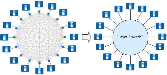
VXLAN virtualizing the entire infrastructure network into a large "Layer 2 virtual switch"
Similar to how a physical server behaves when switched from one port to another port of a physical switch, a VM also does not need to change its IP address when it is migrated from one port of the "Layer 2 virtual switch" to another port.
Sharp Increase in Tenants Raises Demand for Network Isolation
According to standards, a traditional VLAN network supports a maximum of about 4000 VLANs. After server virtualization, a physical server hosts multiple VMs, and each of which has an independent IP address and MAC address. This is equivalent to the number of servers being multiplied. For example, public clouds or other large virtualized cloud data centers need to accommodate tens of thousands of tenants or even more. In this case, VLAN cannot meet these requirements.
How does VXLAN meet these requirements? VXLAN adds a 24-bit VXLAN network identifier (VNI) that is equivalent to a VLAN ID to a VXLAN header. Theoretically, a maximum of 16M VXLAN segments are supported, meeting the requirements for identification and isolation of vast quantities of tenants.
What Are the Differences Between VXLAN and VLAN?
VLAN is a traditional network isolation technology. According to standards, a VLAN network supports a maximum of about 4000 VLANs, failing to meet the requirement for tenant isolation on a large Layer 2 network. In addition, each VLAN is a small and fixed Layer 2 domain, and as such is not suitable for large-scale dynamic VM migration.
VXLAN overcomes these shortfalls of VLAN. In terms of scale, VXLAN uses the 24-bit VNI field to identify up to 16M tenants, far higher than that supported by VLAN (about 4000 tenants). And in terms of flexible migration, VXLAN establishes a virtual tunnel between two switches across the underlying IP network and virtualizes the network into a large "Layer 2 switch" (large Layer 2 network) to meet the requirement for large-scale dynamic VM migration.
Although VXLAN is an extension to VLAN, VXLAN is quite different from VLAN in terms of virtual tunnel establishment.
The following describes what the VXLAN packet looks like.
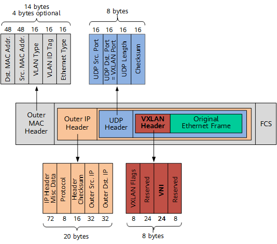
VXLAN packet format (outer IPv4 header used as an example)
As shown in the preceding figure, a VXLAN tunnel endpoint (VTEP) encapsulates the following headers into the original Ethernet frame (original L2 frame) sent by a VM:
- VXLAN header
A VXLAN header (8 bytes) contains a 24-bit VNI field, which is used to define different tenants on the VXLAN network. It also contains a VXLAN Flags field (8 bits, set to 00001000) and two reserved fields (24 bits and 8 bits, respectively).
- UDP header
The VXLAN header and the original Ethernet frame are used as UDP data. In the UDP header, the destination port number (VXLAN Port) is fixed at 4789, and the source port number (UDP Src. Port) is calculated using a hash algorithm based on the original Ethernet frame.
- Outer IP header
In the outer IP header, the source IP address (Outer Src. IP) is the IP address of the VTEP connected to the source VM, and the destination IP address (Outer Dst. IP) is the IP address of the VTEP connected to the destination VM.
- Outer MAC header
The outer MAC header is also called the outer Ethernet header. In this header, the source MAC address (Src. MAC Addr.) is the MAC address of the VTEP connected to the source VM, and the destination MAC address (Dst. MAC Addr.) is the MAC address of the next hop along the path to the destination VTEP.
How Does VXLAN Work?
This section describes how a VXLAN tunnel is established to help you better understand how VXLAN works.
VTEP and VNI in VXLAN
Before understanding how a VXLAN tunnel is established, it is important to be familiar with the common concepts in the VXLAN network model. The following figure shows two servers communicating through a VXLAN network. A VXLAN tunnel is established between two top of rack (TOR) switches to encapsulate the original data frames sent by the source server into VXLAN packets, thereby enabling the original data frames to be transmitted on the bearer network (such as an IP network). When the VXLAN packets arrive at the TOR switch connected to the destination server, the TOR switch decapsulates these packets into the original data frames before finally forwarding these frames to the destination server.
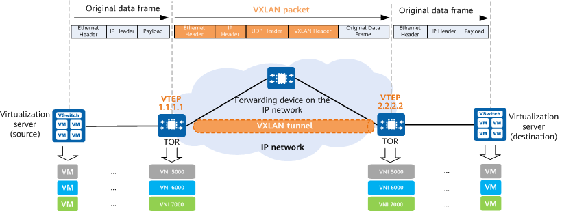
VXLAN network model
VXLAN networks introduce some new elements, such as VTEPs and VNIs. What are their functions? The following introduces these new elements.
What Is a VTEP?
A VTEP is an edge device on a VXLAN network and the start or end point of a VXLAN tunnel. The source VTEP encapsulates the original data frames sent by the source server into VXLAN packets and transmits them to the destination VTEP on the IP network. The destination VTEP then decapsulates the VXLAN packets into the original data frames and forwards the frames to the destination server.
What Is a VNI?
A VNI is a user identifier similar to a VLAN ID. A VNI identifies a tenant. VMs with different VNIs cannot communicate at Layer 2.
VNIs can be classified into Layer 2 VNIs and Layer 3 VNIs, which have different functions. A Layer 2 VNI is a common VNI used for intra-subnet VXLAN packet forwarding, whereas a Layer 3 VNI is bound to a VPN instance for inter-subnet VXLAN packet forwarding.
VXLAN Gateway
Similar to in VLANs, hosts with different VNIs or those on VXLAN and non-VXLAN networks should be unable to directly communicate with each other. To meet these communication requirements, VXLAN introduces VXLAN gateways. VXLAN gateways are classified into Layer 2 gateways and Layer 3 gateways. A Layer 2 VXLAN gateway connects terminals to a VXLAN network and enables intra-subnet communication on a VXLAN network. A Layer 3 VXLAN gateway enables inter-subnet communication on a VXLAN network as well as external network access.
Layer 3 VXLAN gateways can be further categorized into centralized and distributed gateways.
Centralized VXLAN Gateway
In centralized VXLAN gateway networking, the Layer 3 gateway is deployed only on one device. All traffic sent across subnets is forwarded through this Layer 3 gateway, implementing centralized traffic management.
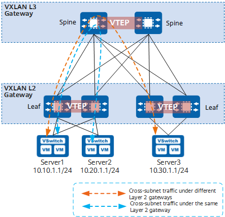
Centralized VXLAN gateway networking
- Advantages: Inter-subnet traffic can be centrally managed, and gateway deployment and management are simplified.
- Disadvantages:
- Forwarding paths are not optimal. Inter-subnet Layer 3 traffic with the same Layer 2 gateway must be transmitted to the centralized Layer 3 gateway for forwarding (shown by the blue dashed line in the preceding figure).
- The ARP entry specification is a bottleneck. ARP entries must be generated for all terminals attached to the Layer 3 gateway. However, the Layer 3 gateway can have only a limited number of ARP entries configured, impeding network expansion.
Distributed VXLAN Gateway
Deploying distributed VXLAN gateways addresses the problems that arise as a result of centralized VXLAN gateway networking. In the spine-leaf networking, leaf nodes function as VTEPs to establish VXLAN tunnels and each can be used as a Layer 3 VXLAN gateway (also a Layer 2 VXLAN gateway). Spine nodes are unaware of the VXLAN tunnels and only forward VXLAN packets between leaf nodes. In the following figure, Server1 and Server2 are on different subnets but connect to the same leaf node. When Server1 and Server2 communicate with each other, their traffic is forwarded directly through this leaf node, without detouring to any spine node.
In distributed gateway deployment:
- Spine node: is used to implement high-speed IP forwarding.
- Leaf node:
- Functions as a Layer 2 VXLAN gateway and connects to physical servers or VMs, allowing tenants to access VXLAN segments.
- Functions as a Layer 3 VXLAN gateway to perform VXLAN encapsulation/decapsulation, allowing for inter-subnet communication and external network access.
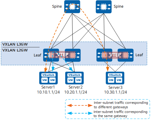
Distributed VXLAN gateway networking
- A leaf node can function as both a Layer 2 VXLAN gateway and a Layer 3 VXLAN gateway, supporting flexible deployment.
- A distributed VXLAN gateway (leaf node) only needs to learn the ARP entries of servers connected to it, whereas a centralized Layer 3 VXLAN gateway needs to learn the ARP entries of all servers on a network. Distributed VXLAN gateways overcome the ARP entry bottleneck, improving network scalability.
Which VTEPs Need to Establish VXLAN Tunnels?
The large Layer 2 network overcomes physical boundaries, allowing VMs on the same large Layer 2 network to communicate with each other. VXLAN tunnels must be established between all VTEPs on the same large Layer 2 network. Assuming that VMs connected to VTEP_1, VTEP_2, and VTEP_3 require large Layer 2 communication on the network shown in the following figure, then VTEP_1, VTEP_2, and VTEP_3 need to establish VXLAN tunnels with each other.
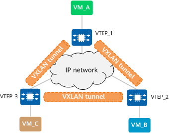
Establishing VXLAN tunnels
VXLAN Tunnel Establishment
A VXLAN tunnel is identified by a pair of VTEP IP addresses. During VXLAN tunnel establishment, the local and remote VTEPs attempt to obtain each other's IP addresses. As long as the VTEP IP addresses are reachable to each other at Layer 3, a VXLAN tunnel can be established.
VXLAN tunnels can be established in either static or dynamic mode.
In static mode, there is no control plane. During VXLAN tunnel establishment, you need to manually specify the IP addresses of the local VTEP and remote VTEP as the VXLAN tunnel's source and destination IP addresses, respectively. The static mode has poor flexibility and requires a lot of manual configuration. For this reason, it is not applicable to large-scale networking scenarios.
In dynamic mode, VXLAN EVPN is used as the VXLAN control plane for VXLAN tunnel establishment. A BGP EVPN peer relationship is established between two VTEPs, and they use VXLAN EVPN routes for purposes such as automatic VTEP discovery and host information advertisement. In this way, VXLAN tunnels are dynamically established. The data plane forwards packets based on the forwarding entries created on the control plane. The dynamic mode has high flexibility and is applicable to large-scale VXLAN networking scenarios.
How Can I Determine the VXLAN Tunnel to Which a Packet Belongs
A large Layer 2 network is similar to a traditional virtual local area network (VLAN). On a VXLAN network, large Layer 2 networks are identified by BD, and BDs are identified by VNI. When establishing a VXLAN tunnel, you need to configure the mapping between BDs and VNIs on VTEPs, based on which the VTEPs determine the VNI to be added to packets during VXLAN encapsulation. The VNI identifies the VXLAN tunnel through which packets are to be forwarded. Given this, how can we determine to which BD a packet belongs?
How Can We Determine to the BD to Which a Packet Belongs?
VTEP is only one of the roles assumed by a device. The device serving as a VTEP also provides other functions. This means that not all packets received by a device are forwarded through a VXLAN tunnel. Rather, it is possible that some packets are forwarded according to the common Layer 2 and Layer 3 forwarding processes. Before determining the BD to which a packet belongs, we need to know which packets will enter a VXLAN tunnel.
Which Packets Will Enter a VXLAN Tunnel?
Before answering this question, let's recall how a device receives and sends packets using VLAN technology. Packets must first be processed by interfaces on the device prior to subsequent processing. Three types of interfaces are defined for traditional networks: access, trunk, and hybrid. Even though the three interface types have different application scenarios, their final goals are the same: to check which packets are allowed to pass through based on configurations, and to determine how to process the packets that are allowed to pass through.
On a VXLAN network, VTEP interfaces have similar responsibilities. The only difference is that these interfaces are logical Layer 2 sub-interfaces, not physical interfaces. Similarly, Layer 2 sub-interfaces provide two functions: One is to check which packets need to enter a VXLAN tunnel based on configurations, and the other is to determine how to process the packets that are allowed to pass through. To simplify configuration management, different packet encapsulation types are defined for Layer 2 sub-interfaces, just like different interface types are defined for traditional networks. Currently, the main traffic encapsulation types are dot1q, untag, qinq, and default:
- dot1q: If a dot1q sub-interface receives single-tagged VLAN packets, it forwards only those packets with a specified VLAN tag. If the sub-interface receives double-tagged VLAN packets, it forwards only those packets with a specified outer VLAN tag.
- untag: This type of sub-interface accepts only packets that do not carry VLAN tags.
- qinq: This type of sub-interface accepts only packets with specified double VLAN tags.
- default: This type of sub-interface accepts all packets, regardless of whether they carry VLAN tags. For VXLAN encapsulation and decapsulation, a default sub-interface does not perform any VLAN tag-related action on the original packets, such as the addition, replacement, and removal of VLAN tags.
In addition to Layer 2 sub-interfaces, VLANs can also be used as service access points. After a VLAN is bound to a BD, the interface added to the VLAN becomes a VXLAN service access point, and packets received by the interface are forwarded to a VXLAN tunnel.
Adding a Layer 2 Sub-Interface to a BD
Now we can easily answer how to determine the BD to which a packet belongs. All we need to do is to add Layer 2 sub-interfaces to specified BDs. Then the BDs to which packets belong can be determined based on the Layer 2 sub-interface configurations.
What Is VXLAN EVPN?
Ethernet Virtual Private Network (EVPN) is a VPN technology used for Layer 2 internetworking. EVPN uses a mechanism similar to BGP/MPLS IP VPN and defines a new type of Network Layer Reachability Information (NLRI), called EVPN NLRI, based on BGP. EVPN NLRI defines several new types of BGP EVPN routes to implement MAC address learning and advertisement between different sites on a Layer 2 network.
In the initial VXLAN framework (defined in RFC 7348), there is no control plane, VXLAN tunnels are manually configured, and VTEP discovery and host information learning are performed through traffic flooding on the data plane. Host information includes IP addresses, MAC addresses, VNIs, and gateway VTEP IP addresses. This framework is easy to implement, but it gives rise to a lot of flooding traffic on the network and complicates network expansion. To solve the preceding problems, VXLAN introduces EVPN as its control plane. Specifically, after EVPN is deployed, VXLAN uses EVPN routes to transmit VTEP addresses and host information, moving VTEP discovery and host information learning from the data plane to the control plane.
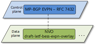
EVPN functioning as the control plane of VXLAN
Using EVPN as the control plane of VXLAN has the following advantages:
- VTEPs can be automatically discovered and VXLAN tunnels can be automatically established, simplifying network deployment and expansion.
- EVPN can advertise both Layer 2 MAC address information and Layer 3 route information.
- Flooding traffic is reduced on the network.
What Are the Route Types of VXLAN EVPN?
EVPN NLRI defines the following types of BGP EVPN routes applicable to the VXLAN control plane:
- Type 2 routes: also called MAC/IP routes, are used by VTEPs to advertise host IP and MAC address information to each other.
- Type 3 routes: used to advertise Layer 2 VNIs and VTEP IP addresses between VTEPs to establish an ingress replication list for forwarding BUM packets.
- Type 5 routes: also called IP prefix routes, are used to transmit prefix routes.
Using EVPN to Advertise VTEP Routes
In an intra-subnet communication scenario, a VXLAN tunnel can be established between two VTEPs so long as the two VTEP IP addresses are reachable to each other. This is because the communication is inside the same Layer 2 BD. When EVPN is used to dynamically establish a VXLAN tunnel, two VTEPs establish a BGP EVPN peer relationship and exchange Type 3 routes to transmit VNI and VTEP IP address information for VXLAN tunnel establishment.
Using EVPN to Advertise Host Routes
In an inter-subnet communication scenario, hosts in different Layer 2 BDs need to communicate with each other over IP route to peer hosts. EVPN Type 2 routes carry host IP addresses with 32-bit masks. VTEPs advertise host routes to each other through EVPN Type 2 routes for Layer 3 forwarding.
Using EVPN to Advertise Subnet Routes
Subnet routes are advertised in a similar way to host routes. The difference is that subnet routes are advertised through Type 5 routes, while Type 2 routes can only be used to advertise 32-bit or 128-bit host routes. Type 5 routes can also be used to advertise 32-bit or 128-bit host routes. When advertising 32-bit or 128-bit host routes, Type 5 routes function similarly to Type 2 routes.
MAC Address Learning Through EVPN
On a VXLAN network, dynamic MAC address learning is required to reduce manual maintenance workload and traffic flooding. Inter-subnet communication requires Layer 3 forwarding, and MAC address learning is implemented using dynamic ARP packets between the local host and gateway. In an intra-subnet communication scenario, EVPN serves as the VXLAN control plane and can be used for MAC address learning. Type 2 routes carry not only IP route information, but also MAC address information. When EVPN is used for MAC address learning, VTEPs exchange Type 2 routes for MAC address learning.
How Are Packets Forwarded on a VXLAN Network?
In conventional forwarding, Layer 2 forwarding depends on the MAC address table, and Layer 3 forwarding depends on the FIB table. This also holds true on a VXLAN network. The following uses a VXLAN tunnel establishment) as an example to describe how intra-subnet and inter-subnet communication is implemented, helping you understand VXLAN concepts.
Intra-subnet communication on a centralized VXLAN network
As shown in the following figure, VM_A, VM_B, and VM_C belong to the same subnet. VM_A needs to communicate with VM_C. The packet processing for first-time communication is as follows:
- VM_A broadcasts an ARP Request packet to request VM_C's MAC address.
- After receiving the ARP Request packet, VTEP_1 performs VXLAN encapsulation on the packet, replicates it into multiple copies, and sends a copy to each peer VTEP.
- After the packet arrives at VTEP_2 and VTEP_3, the VTEPs decapsulate the packet to obtain the original packet sent by VM_A. VTEP_2 and VTEP_3 broadcast the packet in the corresponding Layer 2 domains.
- After the ARP Request packet reaches VM_C, VM_C finds that the destination IP address of the packet is the same as its own IP address. Therefore, VM_C sends an ARP Reply packet in response. Other VMs, however, discard the received ARP Request packet.
After the preceding process is complete, VM_A and VM_C learn each other's MAC address. After that, VM_A and VM_C will communicate in unicast mode.
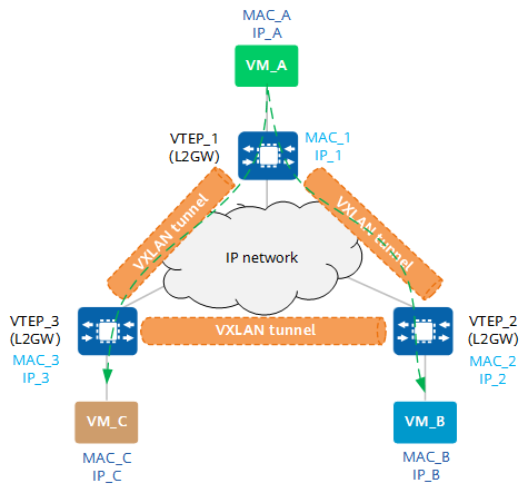
Communication between VMs on the same subnet
Inter-Subnet Communication on a Centralized VXLAN Network
Inter-subnet packet forwarding requires Layer 3 gateways. As shown in the following figure, VM_A and VM_B belong to different subnets. The packet processing for communication between VM_A and VM_B is as follows:
- VM_A sends a data packet to VTEP_1.
- After receiving the VXLAN packet, VTEP_1 performs VXLAN encapsulation on the packet and sends the VXLAN packet to VTEP_3.
- After the VXLAN packet arrives at VTEP_3, it decapsulates the packet and finds that the destination MAC address is MAC_10 (MAC address of the Layer 3 gateway interface BDIF) and the destination IP address is IP_B (10.1.20.1). This means that this packet requires Layer 3 forwarding.
- VTEP_3 finds the next hop of IP_B based on the routing table and finds that the outbound interface is BDIF 20. VTEP_3 then performs VXLAN encapsulation on the packet and sends it to VTEP_2.
- After the packet reaches VTEP_2, VTEP_2 decapsulates the packet and sends it to VM_B.
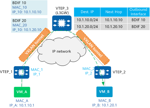
Communication between VMs on different subnets

A BDIF interface is similar to a VLANIF interface. That is, a BDIF interface is a logical Layer 3 interface created based on a BD to achieve communication between different subnets or between VXLAN and non-VXLAN networks.
- Author: Zhang Yuting, Chen Li
- Updated on: 2024-01-23
- Views: 39509
- Average rating:


