What Is ARP?
Address Resolution Protocol (ARP) is a protocol used to map IP addresses to MAC addresses. It is therefore necessary for hosts or Layer 3 network devices to maintain an ARP table for storing the mapping information of IP and MAC addresses. There are generally two types of ARP entries: static and dynamic.
Why Do We Need ARP?
ARP is required to map IP addresses to MAC addresses.
For hosts or other Layer 3 network devices to communicate on a LAN, the sender must know the destination IP address to which it will send IP packets. The IP packets, however, must first be encapsulated with MAC addresses before they can be transmitted over the physical network. It is therefore necessary for hosts or Layer 3 network devices to maintain an ARP table for storing the mapping information of IP and MAC addresses.
What Are the Types of ARP?
Dynamic ARP
Dynamic ARP entries are automatically generated and maintained when ARP packets are sent and received. They can be aged, updated, or overwritten by Static ARP entries.
Dynamic ARP applies to complex networks that transmit delay-sensitive services.
Static ARP
Static ARP allows a network administrator to manually create the fixed mappings between IP and MAC addresses. Static ARP entries cannot be aged or overwritten by dynamic ARP entries, ensuring system security.
In most cases, devices on a network can use ARP to dynamically learn ARP entries and age or update the generated dynamic ARP entries. However, when a network encounters an ARP attack, the dynamic ARP entries may be incorrectly updated or aged. As a result, the communication between authorized users becomes abnormal.
Static ARP entries can be neither aged nor overwritten by dynamic ARP entries, ensuring communication security. If a static ARP entry is configured on a device, the device can communicate with the peer device using only the specified MAC address. Network attackers cannot modify the mapping between the IP and MAC addresses using ARP packets, ensuring communication between the two devices. Static ARP entries are generally configured on gateways.
Short static ARP entries
A network administrator manually creates the mappings between IP and MAC addresses without specifying any VLAN and outbound interface.
If the outbound interface is a Layer 2 Ethernet interface, short static ARP entries cannot be directly used to forward packets.
To forward a packet, the device has to send an ARP Request packet first. If the source IP and MAC addresses in the received ARP Reply packet are the same as those in the configured static ARP entry, the device adds the VLAN and interface that receive the ARP Reply packet to this static ARP entry. The device can use this static ARP entry to forward subsequent packets.
Long static ARP entries
A network administrator manually creates the mappings between IP and MAC addresses, and also specifies VLANs and outbound interfaces through which the device sends packets.
Long static ARP entries can be directly used to forward packets and are therefore recommended.
Gratuitous ARP
Gratuitous ARP allows a device to send an ARP Request packet that carries its own IP address as the destination IP address.
Gratuitous ARP has the following functions:
Checks for IP address conflicts.
When the protocol status of a device interface changes to Up, the device broadcasts gratuitous ARP packets. If the device receives an ARP reply, another device is using the same IP address. When detecting an IP address conflict, the device periodically broadcasts gratuitous ARP Reply packets until the conflict is removed.
Advertises a new MAC address.
If the MAC address of a device is changed because its network adapter is replaced, the device sends a gratuitous ARP packet to notify all devices of the change before the ARP entry is aged out.
Notifies other devices of a master/backup switchover in a VRRP group.
After a master/backup switchover, the master device broadcasts a gratuitous ARP packet in the VRRP group to notify other devices of the switchover.
Proxy ARP
Proxy ARP is a technique in which a device on a given network answers the ARP requests for a network address that is not on that network.
- Proxy ARP is deployed on the gateway without any modifications to the configurations of the hosts on a network.
- Proxy ARP can shield topologies of physical networks so that hosts on different physical networks can use the same network ID to communicate.
- Proxy ARP affects only the ARP tables on hosts and does not affect the ARP table and routing table on the gateway.
Routed Proxy ARP
Routed proxy ARP enables communication among network devices on the same network segment but on different physical networks.
If a host connected to a device is not configured with a default gateway address, the host does not know how to reach the intermediate system of the network. Therefore, data forwarding cannot be performed. Routed proxy ARP resolves this problem.
As shown in the following figure, Host_1 and Host_2 are located on the same network segment. The Switch connects two networks through VLANIF 10 and VLANIF 20. The IP addresses of VLANIF 10 and VLANIF 20 are located on different network segments.
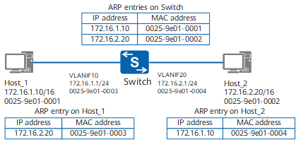
The IP addresses of Host_1 and Host_2 are on the same network segment. When Host_1 needs to communicate with Host_2, Host_1 broadcasts an ARP Request packet, requesting the MAC address of Host_2. However, Host_1 and Host_2 are on different physical networks (in different broadcast domains); therefore, Host_2 cannot receive the ARP Request packet sent from Host_1 and does not respond with an ARP Reply packet.
With routed proxy ARP enabled on the Switch, the Switch queries the routing table after receiving the ARP Request packet. Host_2 is directly connected to the Switch, so the Switch has the routing entry of Host_2. The Switch then uses its MAC address to send an ARP Reply packet to Host_1. Host_1 forwards data based on the MAC address of the Switch. In this case, the Switch functions as the proxy of Host_2. This is shown in figure, where the MAC address mapped to Host_2's IP address in the ARP table of Host_1 is the MAC address of VLANIF 10 on the Switch.
Networking diagram of routed proxy ARP
Intra-VLAN Proxy ARP
If two users belong to the same VLAN (which has port isolation configured), enabling intra-VLAN proxy ARP on the VLAN-associated interfaces allows the hosts to communicate at Layer 3.
As shown in the following figure, Host_1 and Host_2 are connected to the Switch. The two interfaces connected to Host_1 and Host_2 belong to VLAN 10 on the Switch.
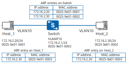
Host_1 and Host_2 cannot communicate at Layer 2 because port isolation in a VLAN is configured on the Switch.
However, with intra-VLAN proxy ARP enabled on the Switch's interface, Host_1 and Host_2 can communicate at Layer 3. After the Switch's interface receives an ARP Request packet whose destination address is not its own address, the Switch searches for the ARP entry matching the interface. If an ARP entry matches Host_2, the Switch sends its own MAC address to Host_1 and forwards the packet destined for Host_2. In this case, the Switch functions as the proxy of Host_2.
Network diagram of intra-VLAN proxy ARP
Inter-VLAN Proxy ARP
If two hosts belong to the same network segment but different VLANs, enabling inter-VLAN proxy ARP on the VLAN-associated interfaces (for example, the VLANIF interfaces or sub-interfaces) allows users to communicate at Layer 3.
As shown in the following figure, Host_1 and Host_2 on the same network segment are connected to the Switch, Host_1 belongs to sub-VLAN 10, and Host_2 belongs to sub-VLAN 20.
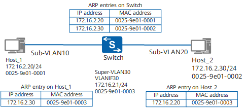
Host_1 and Host_2 belong to different sub-VLANs, so they cannot communicate at Layer 2.
However, with inter-VLAN proxy ARP enabled on the Switch, Host_1 and Host_2 can communicate at Layer 3. After the Switch's interface receives an ARP Request packet whose destination address is not its own address, the Switch searches for the ARP entry (a dynamically learned or statically configured ARP entry) matching Host_2. If an ARP entry matches Host_2, the Switch sends its own MAC address to Host_1 and forwards the packet destined for Host_2. In this case, the Switch functions as the proxy of Host_2.
Network diagram of inter-VLAN proxy ARP
How Does ARP Work?
Dynamic ARP broadcasts ARP Request packets and unicasts ARP Reply packets to complete address resolution.
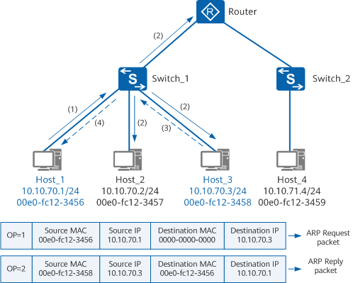
Address resolution process
As shown in the figure, Host_1 and Host_3 are on the same network segment, and Host_1 needs to communicate with Host_3.
- Host_1 searches its local ARP table for the ARP entry of Host_3. If the MAC address of Host_3 is found, Host_1 uses this MAC address to encapsulate the data packet into a frame and sends it to Host_3. If Host_1 does not find the MAC address of Host_3, Host_1 caches the data packet and broadcasts an ARP Request packet.
- Switch_1 receives the ARP Request packet and forwards it across the appropriate broadcast domain.
- Host_2 and Host_3 in that broadcast domain both receive the ARP Request packet. Because Host_3 finds that the destination IP address of the ARP Request packet is its own IP address, it adds the source IP and MAC addresses of the ARP Request packet to its own ARP table. It then unicasts an ARP Reply packet to Host_1.
- Switch_1 receives the ARP Reply packet and forwards it to Host_1. Upon receipt, Host_1 adds the MAC address of Host_3 to its ARP table. It then encapsulates the data packet into a frame and forwards it to Host_3.
As shown in the figure, Host_1 and Host_4 are on different network segments, and a default gateway address (the Router's IP address) has been set on Host_1. If Host_1 and Host_4 need to communicate, Host_1 must first discover the Router's MAC address. The process for Host_1 to learn the Router's MAC address and for the Router to learn Host_4's MAC address is similar to that between Host_1 and Host_3. When the data packet from Host_1 arrives at the Router, the Router forwards the packet to Host_4.
ARP Aging Mechanism
As shown in the figure above, if Host_1 broadcasts an ARP Request packet every time it sends data to Host_3, network communication traffic will greatly increase. Furthermore, all other hosts on the network have to receive and process the ARP Request packets, which lowers network efficiency. To resolve this problem, each host or device maintains a high-speed cache that stores the recently learned IP-to-MAC mappings (namely, dynamic ARP entries).
A host or device first queries the local high-speed cache for the IP-to-MAC mappings every time it sends a packet. If the MAC address is found, the host or device no longer sends an ARP Request packet but directly sends the data packet to the MAC address. If the MAC address is not found, the host or device broadcasts an ARP Request packet for address resolution.
Devices age and update dynamic ARP entries to ensure that the capacity limit of the ARP tables is not exceeded and that the ARP entries in the table are correct.
The aging parameters of a dynamic ARP entry include the aging time, number of aging probe attempts, and aging probe mode. After the aging time of a dynamic ARP entry expires, the device sends an aging probe packet (ARP Request packet) to detect whether the peer device is present. If the device receives an ARP Reply packet, it updates this dynamic ARP entry. If the device does not receive an ARP Reply packet, it deletes the dynamic ARP entry.
The aging probe packet can be a unicast or broadcast packet. By default, the device only broadcasts the last ARP aging probe packet to the peer host or device, and unicasts other ARP aging probe packets. When the MAC address of the peer device is fixed, an interface can be configured to unicast ARP aging probe packets.
If the interface goes Down, the device immediately deletes the interface's dynamic ARP entries.
ARP Packet Format
The length of an ARP packet is 42 bytes. The first 14 bytes represent an Ethernet frame header, and the last 28 bytes contain the ARP packet information.
Figure Format of an ARP Request or Reply packet shows the format of an ARP packet.

Format of an ARP Request or Reply packet
Figure Fields within an ARP packet describes the fields within an ARP packet.
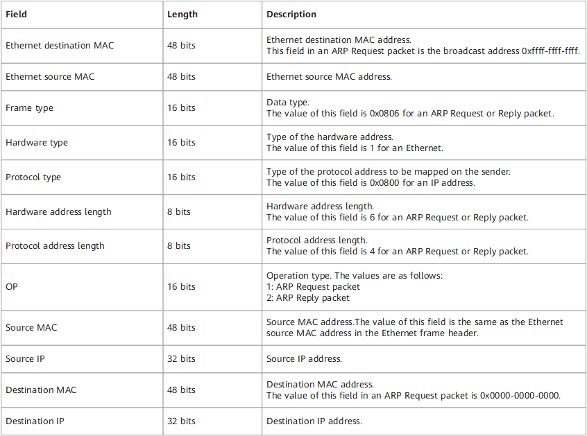
Fields within an ARP packet
- Author: Li jiyuan
- Updated on: 2021-12-07
- Views: 18084
- Average rating:


