What Is Super VLAN?
Super VLAN, also called VLAN aggregation, partitions a broadcast domain on a physical network into multiple VLANs (sub-VLANs) and aggregates them into a single logical VLAN (super-VLAN). The sub-VLANs are addressed from the same IP subnet and share a default gateway address, thereby reducing the number of IP addresses required on the network.
Why Do We Need Super VLAN?
VLAN technology is commonly used on packet-switched networks because it facilitates network design. For example, it can split a large broadcast domain into smaller ones, group hosts together regardless of their location, and separate hosts, resources, and traffic. However, communication between hosts in different broadcast domains typically requires a Layer 3 switch to be configured with a Layer 3 logical interface per VLAN. This wastes IP addresses because each VLAN requires a unique subnet ID, directed broadcast address, and subnet default gateway address, none of which can be assigned as a host's IP address. In addition, the IP address block allocated to a VLAN may contain more IP addresses than required. Unused IP addresses in one VLAN cannot be used in other VLANs.
For example, in the following figure, VLAN 2 contains 10 hosts. The VLAN is assigned the subnet 10.1.1.0/28, which provides 16 IP addresses. Of these addresses, 10.1.1.0 is the subnet ID, 10.1.1.15 is the directed broadcast address, and 10.1.1.1 is the default gateway address. The remaining 13 IP addresses are available for the 10 hosts, leaving three wasted IP addresses that cannot be used in other VLANs.
At least three IP addresses are wasted for VLAN 2, and at least nine IP addresses are wasted for three VLANs. Although VLAN 2 requires only 10 IP addresses, the remaining 3 IP addresses cannot be used by other VLANs and are wasted. If more VLANs are added, the problem is exacerbated.
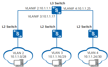
Common VLAN scenario
To solve the preceding problem, VLAN aggregation can be used. VLAN aggregation maps each sub-VLAN to a broadcast domain, associates a super-VLAN with multiple sub-VLANs, and assigns only one IP subnet to the super-VLAN. Consequently, the gateway IP address of all sub-VLANs is the IP address of the associated super-VLAN.
By sharing the gateway address, the number of subnet IDs, subnet default gateway addresses, and directed broadcast IP addresses used is reduced. The switch assigns IP addresses to hosts in sub-VLANs according to the number of hosts. This ensures that each sub-VLAN acts as an independent broadcast domain, conserves IP addresses, and implements flexible addressing.
What Are Application Scenarios of Super VLAN?
In the following figure, an enterprise has multiple departments that connect to the Internet through different switches. For security purposes, the enterprise adds different departments to different VLANs. However, the number of available IP addresses is limited.
The requirements are as follows:
- All departments require access to the Internet.
- Department 1 and department 2 need to communicate with each other.
- Department 3 and department 4 need to communicate with each other.
Layer 2 communication between hosts in sub-VLANs and on an external network
VLAN aggregation and proxy ARP can be used to meet the preceding requirements. Deploy super-VLAN 2 and super-VLAN 3 on the switch, and add sub-VLAN 21 and sub-VLAN 22 to super-VLAN 2 and sub-VLAN 31 and sub-VLAN 32 to super-VLAN 3. After IP addresses are assigned to super-VLAN 2 and super-VLAN 3 on the switch, users in department 1 and department 2 can access the Internet using the IP address of super-VLAN 2, and users in department 3 and department 4 can access the Internet using the IP address of super-VLAN 3.
Therefore, VLAN aggregation allows all departments to access the Internet access and conserves IP addresses.
To allow communication between departments 1 and 2 and departments 3 and 4, configure proxy ARP on the switch in super-VLAN 2 and super-VLAN 3.
How Does Super VLAN Work?
Implementation
VLAN aggregation introduces the concept of sub-VLANs and super-VLANs. A sub-VLAN is an independent broadcast domain that contains only physical interfaces, whereas a super-VLAN contains no physical interface and is used for creating a Layer 3 VLANIF interface. By mapping a super-VLAN to sub-VLANs, VLAN aggregation associates the Layer 3 VLANIF interface with physical interfaces. This allows all sub-VLANs to share one gateway to communicate with an external network. In addition, proxy ARP can be used to implement Layer 3 connectivity between sub-VLANs. Super-VLANs and sub-VLANs differ from common VLANs that contain a Layer 3 logical interface and multiple physical interfaces.
- Sub-VLAN: contains only physical interfaces, and is used to isolate broadcast domains. A sub-VLAN cannot be used to create a Layer 3 VLANIF interface. Hosts in each sub-VLAN use the VLANIF interface of the associated super-VLAN for Layer 3 communication with external devices.
- Super-VLAN: contains no physical interfaces, and is used only for creating a Layer 3 VLANIF interface. The VLANIF interface remains Up providing that at least one physical interface in any associated sub-VLAN is Up. A super-VLAN can contain one or more sub-VLANs, which use its IP address as their subnet gateway.
In a super-VLAN, each host, no matter which sub-VLAN it belongs, is allocated an IP address from the subnet segment associated with the super-VLAN (a sub-VLAN does not occupy an independent subnet). Therefore, sub-VLANs share the same gateway.
VLAN aggregation reduces the number of required subnet IDs, subnet default gateway addresses, and directed broadcast IP addresses. It allows different broadcast domains to use the same subnet address, allows for flexible addressing, and conserves IP addresses.
Consider the following example. In the following figure, VLAN 10 is configured as the super-VLAN and assigned the subnet address 10.1.1.0/24. VLAN 2, VLAN 3, and VLAN 4 are configured as sub-VLANs of super-VLAN 10.
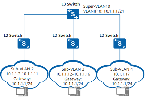
VLAN aggregation scenario
Sub-VLAN 2, sub-VLAN 3, and sub-VLAN 4 share a subnet (10.1.1.0/24). The subnet ID (10.1.1.0), default gateway address (10.1.1.1), and directed broadcast address of the subnet (10.1.1.255) cannot be used as host IP addresses. VLAN aggregation allows the switch to assign IP addresses to hosts in sub-VLANs according to the actual number of hosts. For example, if sub-VLAN 2 contains only 10 hosts, the switch allocates IP addresses 10.1.1.2 to 10.1.1.11 to sub-VLAN 2.
Communication Between Sub-VLANs
VLAN aggregation allows hosts in different sub-VLANs to communicate at Layer 2 but not at Layer 3. To enable Layer 3 communication between hosts in different sub-VLANs, configure proxy ARP.
The following figure shows an example of using proxy ARP to implement Layer 3 communication between sub-VLANs. To allow Host_1 in sub-VLAN 2 to communicate with Host_2 in sub-VLAN 3, enable proxy ARP on the VLANIF interface of super-VLAN 10.
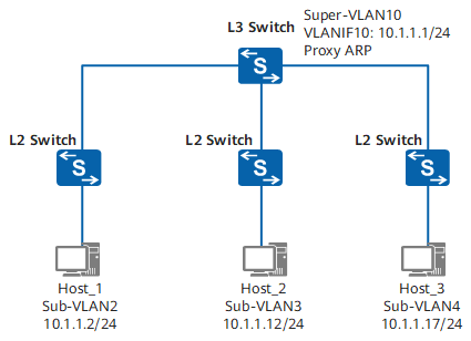
Using proxy ARP to implement Layer 3 communication between sub-VLANs
Host_1 communicates with Host_2 as follows (assume that the ARP table of Host_1 has no entry for Host_2):
- Host_1 compares the IP address of Host_2 with its IP address, and finds that both IP addresses are on the same network segment 10.1.1.0/24. However, the ARP table of Host_1 has no entry for Host_2.
- Host_1 broadcasts an ARP Request packet with the destination IP address of 10.1.1.12 to request the MAC address of Host_2.
- The Layer 3 switch (gateway) is enabled with proxy ARP between sub-VLANs. After receiving the ARP Request packet from Host_1, the Layer 3 switch searches its routing table for the destination IP address in the ARP Request packet. The Layer 3 switch finds a matched route in its routing table where the next-hop address is the directly connected network segment (10.1.1.0/24 of VLANIF 10). The Layer 3 switch then broadcasts an ARP Request packet to all sub-VLANs in super-VLAN 10, requesting the MAC address of Host_2.
- After receiving the ARP Request packet, Host_2 sends an ARP Reply packet.
- After receiving the ARP Reply packet, the Layer 3 switch encapsulates the ARP Reply packet with its MAC address and sends it to Host_1.
- Subsequent packets sent by Host_1 to Host_2 are first sent to the gateway. The gateway then forwards the packets across Layer 3.
The packets sent by Host_2 to Host_1 are processed in the same way as the packets sent by Host_1 to Host_2.
Layer 3 Communication Between Hosts in Sub-VLANs and on an External Network
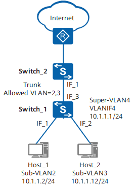
The following figure shows an example, user hosts and servers reside on different network segments. Sub-VLANs 2 to 4 and VLAN 10 are configured on Switch_1, and VLAN 10 and VLAN 20 are configured on Switch_2.
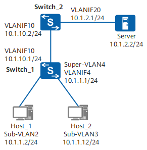
Layer 3 communication between hosts in sub-VLANs and on an external network
- Host_1 compares the server's IP address (10.1.2.2) with its network segment 10.1.1.0/24 and finds that they are on different network segments. Host_1 then sends an ARP Request packet to its gateway to request the gateway's MAC address. The ARP Request packet carries an all-F (broadcast) destination MAC address and destination IP address 10.1.1.1.
- After receiving the ARP Request packet, Switch_1 searches its ARP table for a mapping between the super-VLAN and sub-VLANs. Switch_1 then sends an ARP Reply packet with the MAC address of VLANIF 4 (corresponding to super-VLAN 4) from an interface of sub-VLAN 2 to Host_1.
- After learning the gateway's MAC address, Host_1 sends a packet with the MAC address of VLANIF 4 (corresponding to super-VLAN 4) as the destination MAC address and a destination IP address of 10.1.2.2.
- After receiving the packet from Host_1, Switch_1 determines that the packet should be forwarded at Layer 3 according to the mapping between the super-VLAN and sub-VLANs and the destination MAC address. Switch_1 then searches its Layer 3 forwarding table for a matching entry, but none is found. Consequently, Switch_1 sends the packet to the CPU. The CPU searches its routing table and obtains the next-hop address of 10.1.10.2 and the outbound interface of VLANIF 10. Switch_1 determines the outbound interface according to the ARP entry and MAC address entry, and sends the packet to Switch_2.
- Switch_2 sends the packet to the server through Layer 3 forwarding.
- Switch_2 sends the response packet to Switch_1 through Layer 3 forwarding. At Switch_1, the destination MAC address contained in the packet is changed to the MAC address of VLANIF 10 on Switch_1.
- After receiving the packet, Switch_1 determines that the packet should be forwarded at Layer 3 according to the destination MAC address. Switch_1 then searches its Layer 3 forwarding table for a matching entry, but none is found. Consequently, Switch_1 sends the packet to the CPU. The CPU searches its routing table and obtains the next-hop address of 10.1.1.2 and the outbound interface of VLANIF 4. Switch_1 searches the mapping between the super-VLAN and sub-VLANs and determines that the packet should be sent to Host_1 from an interface in sub-VLAN 2 according to the ARP entry and MAC address entry.
- The response packet reaches Host_1.
Layer 2 Communication Between Hosts in Sub-VLANs and Other Devices
- Sub-VLAN 2, sub-VLAN 3, and super-VLAN 4 are configured on Switch_1.
- IF_1 and IF_2 on Switch_1 are access interfaces.
- IF_3 is a trunk interface that allows both VLAN 2 and VLAN 3.
- The interface of Switch_2 connected to Switch_1 is a trunk interface and allows both VLAN 2 and VLAN 3.
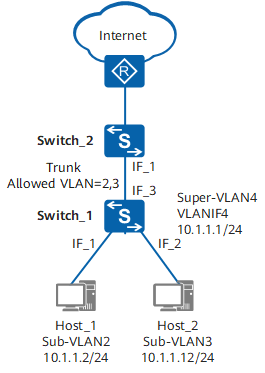
Layer 2 communication between hosts in sub-VLANs and on an external network
For packets sent from Host_1 to Switch_1, a tag with VLAN 2 is added to the packets. This tag remains the same when Switch_1 sends these packets from its IF_3 interface even though sub-VLAN 2 belongs to super-VLAN 4.
Switch_1 does not send packets from VLAN 4. If Switch_1 receives packets from VLAN 4, it discards them because it has no physical interface corresponding to super-VLAN 4. In addition, IF_3 on Switch_1 does not allow packets from super-VLAN 4. In the preceding figure, only sub-VLAN 2 and sub-VLAN 3 are valid.
When VLAN aggregation is configured on Switch_1, communication between Switch_1 and other devices is similar to Layer 2 communication without super-VLAN.
- Author: Gu Suqin
- Updated on: 2021-11-15
- Views: 9265
- Average rating:


