What Is iPCA2.0?
Packet Conservation Algorithm for Internet 2.0 (iPCA 2.0) is an upgrade to iPCA, a technology that measures IP network performance. iPCA directly marks service packets to measure network-level and device-level packet loss.
Why Do We Need iPCA2.0?
Traditional network measurement technologies, such as the frequently used Y.1731 and NQA, are indirect measurement technologies. In other words, these technologies require the sending of additional measurement packets that simulate real service packets to indirectly obtain network quality measurement data. Therefore, the data obtained using these technologies cannot accurately reflect the actual service quality. In addition, the additional measurement packets increase the traffic volume on the network.
iPCA directly marks service packets to perform measurement without extra costs. Therefore, the data obtained using iPCA can reflect the actual service quality. This method is also called in-band flow measurement.
iPCA uses color bits to mark packets. For example, bits in the ToS or Flags field of the IPv4 header can be used as color bits. For details, see the description of Color Bit.
iPCA 2.0 and iPCA have the same measurement principles but different configuration logic. iPCA 2.0 can be used in Huawei CloudCampus Solution. Compared with iPCA, iPCA 2.0 has the following advantages:
First, iPCA 2.0 has a simple configuration model and a visualized configuration process. iPCA 2.0 configurations can be delivered on the GUI of Huawei iMaster NCE-Campus, whereas iPCA configurations must be performed on devices one by one using commands after you log in to the devices.
Second, iPCA 2.0 measurement results and packet loss causes are visible. iPCA packet loss measurement results can only be viewed using display commands on devices, and the command outputs contain only the packet loss rate. O&M personnel need to locate the packet loss cause based on experience. iPCA 2.0 allows devices to periodically (every 1 minute by default) report packet loss and delay measurement results as well as packet loss causes to CampusInsight, an intelligent O&M platform. CampusInsight highlights the packet loss path and devices on the GUI and provides troubleshooting suggestions based on the packet loss causes.
Third, iPCA 2.0 supports service flow identification based on both 5-tuple information and application names for fault locating, whereas iPCA supports service flow identification based only on 5-tuple information for fault locating.
Fourth, iPCA 2.0 can locate faults on both wired and wireless networks, implementing end-to-end fault locating.
What Are Application Scenarios of iPCA2.0?
On an intelligent campus network, users want to use iMaster NCE-CampusInsight to monitor network traffic in real time to quickly detect abnormal traffic and locate faults. iPCA 2.0 can be configured on devices through iMaster NCE-Campus or using the CLI to enable devices to periodically send packet loss and delay measurement information to iMaster NCE-CampusInsight for summary, analysis, and display.
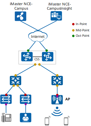
iPCA2.0 Typical Networking Scenarios
How Does It Locate Faults?
iPCA 2.0 colors packets to identify measurement flows. You can configure different measurement points on network devices to obtain measurement data. The following figure illustrates the three parts of the network packet loss and delay measurement model: measurement flow, measurement point, and measurement direction. The following describes several related concepts.
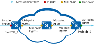
Network packet loss and delay measurement model
Color Bit
A color bit is also called a characteristic bit. Bits in the Type of Service (ToS) or Flags field of the IPv4 header can be used as color bits. The following figure shows the positions of ToS and Flags fields in the IPv4 header.

Color bits
ToS field
The ToS field contains eight bits. The leftmost three bits (bits 0 to 2) constitute the Precedence field that identifies the IP packet priority. Bits 3 to 7 are rarely used, and can therefore be used as color bits.
In RFC 2474, the ToS field in the IPv4 header is redefined as the Differentiated Service (DS) field. In the DS field, the leftmost six bits (bits 0 to 5) are used as the DS Code Point (DSCP), and the rightmost two bits (bits 6 and 7) are reserved. Therefore, when the DS field is used to provide differentiated services, configuring bits 3 to 5 as color bits is not recommended because the measurement result may be inaccurate.
Flags field
The Flags field determines whether a packet can be fragmented. It contains three bits, bits 0 to 2, of which bit 0 is reserved and can be used as the color bit.
Measurement Flow
A measurement flow contains service packets for which packet loss and delay measurement is performed, and it must be specified before each measurement. You can specify the 5-tuple information or application name to determine a measurement flow.
Specifying a Measurement Flow by 5-tuple
The fields of the IP header listed in the following figure identify a unique measurement flow, which can be specified by any combination of these fields. However, it is difficult to accurately determine a measurement flow if only some of these fields are specified. Therefore, you are advised to use the combination of multiple fields to accurately determine a measurement flow, thereby ensuring an accurate measurement result.
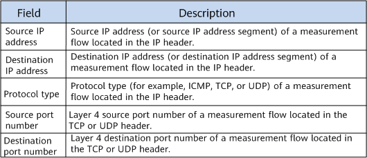
Fields defining measurement flows
Specifying a Measurement Flow by Application Name
After application identification is enabled on an interface of the device (that is, the Intelligent Awareness Engine (IAE) is enabled, the application signature database is loaded, and the service awareness function is enabled), the device extracts the 5-tuple information of packets and compares it with information in the application signature database to search for the app ID that matches the 5-tuple. The device then identifies the application name based on the app ID to determine a measurement flow.
Measurement Point
On a network, measurement points are classified into in-point, mid-point, and out-point based on the packet forwarding direction. Different interfaces on a device can function as different measurement points for measurement.
- In-point: indicates the ingress measurement point of a measurement flow. An in-point colors a measurement flow.
- Mid-point: indicates a transit measurement point of a measurement flow. A mid-point does not color a measurement flow or remove the color bit from it.
- Out-point: indicates the egress measurement point of a measurement flow. An out-point removes the color bit from a measurement flow.
Measurement Direction
Measurement can be performed for packets in both the ingress and egress directions of an interface on the device. A network where measurement can be performed on a mid-point for incoming packets or on another mid-point for outgoing packets.
Fundamentals of Network Packet Loss Measurement
Packet loss measurement allows you to obtain the number of lost packets and the packet loss rate based on the difference between the number of packets entering and leaving the network within a measurement interval.
iPCA 2.0 measures packet loss based on color bits. To be specific, iPCA 2.0 periodically sets and resets a certain color bit in service packet headers on the ingress interface to measure packet loss based on the measurement interval.
On the network shown in the following figure, the number of packets received by Switch_1 is P1, and the number of packets sent by Switch_2 is P2. The difference between P1 (the number of packets entering the network) and P2 (the number of packets leaving the network) is the number of packets discarded on the network within the measurement interval.
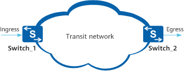
Network packet loss measurement
On the network shown in the above figure, a measurement flow enters the network from Switch_1 and leaves the network from Switch_2. The following figure shows how packet loss measurement is implemented on each device from the time when packets enter the network to the time when the packets leave the network.

Packet loss measurement method
- t0: Switch_1 sets the color bit in incoming service packets to 1, and starts the counter to count the service packets with color bit 1 received within this measurement interval.
- t1: The egress interface of Switch_2 receives the first service packet with color bit 1 in this measurement interval, and starts the counter to count such packets.
- t2: Switch_1 finishes counting the incoming service packets with color bit 1 in this measurement interval, and obtains the number (P1) of packets received within this interval.
- t3: Switch_2 finishes counting all the service packets with color bit 1 in this measurement interval, and obtains the number (P2) of packets sent within this interval. The egress interface of Switch_2 removes the color bit from outgoing service packets.
The number of lost packets within this measurement interval is calculated using LostPacket = P1 - P2.
Fundamentals of Network Delay Measurement
Delay measurement allows you to obtain the forwarding delay between two specified network nodes based on the difference between the time a service flow enters the network and the time it leaves the network within a measurement interval.
iPCA 2.0 measures the delay based on color bits. To be specific, iPCA 2.0 periodically sets and resets a certain color bit in service packet headers on the ingress interface to measure the delay based on the measurement interval.
On the network shown in the following figure, the time when Switch_1 sends a service flow and the time when Switch_2 receives the service flow are recorded, and the difference between them is the network delay.
The accuracy of one-way delay measurement depends on high-precision time synchronization between devices on the network, which means low-precision time synchronization will result in a large delay measurement error. To minimize the delay measurement error, iPCA 2.0 uses two-way delay measurement.
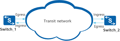
Network delay measurement
Delay Measurement Method
On the network shown in the above figure, the packet forwarding delay is obtained by comparing the time Switch_1 sends a service flow, the time Switch_2 receives the service flow, the time Switch_2 sends a return flow, and the time Switch_1 receives the return flow. The following figure shows how delay measurement is implemented from the time Switch_1 sends packets to the time Switch_2 receives the packets.
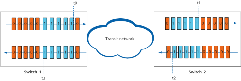
Delay measurement method
- t0: Switch_1 sets the color bit in sent service packets to 1 and starts the counter to record the packet sending time.
- t1: Switch_2 receives the first service packet with color bit 1 in this measurement interval and records the packet receiving time.
- t2: Switch_2 sets the color bit in the return packet to 1 and starts the counter to record the packet sending time.
- t3: Switch_1 receives the first return packet with color bit 1 in this measurement interval and records the packet receiving time.
The one-way delay between Switch_1 and Switch_2 are calculated using 1d (Switch_1 -> Switch_2) = t1 - t0 and 1d (Switch_2 -> Switch_1) = t3 - t2. The two-way delay is calculated using 2d = (t1 - t0) + (t3 - t2) = (t3 - t0) - (t2 - t1).
Automatic In-Band Flow Measurement
In automatic in-band flow measurement, a measurement flow is specified only on the in-point, and no measurement flow needs to be specified on the mid-point and out-point. Devices automatically obtain measurement flow information based on the color bit set on the upstream device and create measurement entries.
On the network shown in the following figure, a measurement flow is configured (by specifying the 5-tuple) on Switch_1 and the inbound interface on Switch_1 is configured as an in-point to perform packet loss and delay measurement for incoming packets. The outbound interface on Switch_1 and interfaces on Switch_2 and Switch_3 are configured as measurement points for automatic in-band flow measurement. The automatic in-band flow measurement process in which packets are forwarded from Switch_1 to Switch_3 is as follows:
- After packets enter Switch_1, Switch_1 identifies the measurement flow based on 5-tuple information. The inbound interface on Switch_1 colors incoming packets and performs measurement for them.
- The outbound interface on Switch_1 forwards the packets. Being configured with automatic in-band flow measurement, the interface automatically identifies packets with color bit 1, creates a measurement entry, and performs measurement.
- The packets are forwarded to Switch_2. Being configured with automatic in-band flow measurement, the inbound and outbound interfaces on Switch_2 automatically identify packets with color bit 1, create measurement entries, and perform measurement.
- The packets are forwarded to Switch_3. Being configured with automatic in-band flow measurement, the inbound and outbound interfaces on Switch_3 automatically identify packets with color bit 1, create measurement entries, and perform measurement. Being configured as an out-point, the outbound interface on Switch_3 removes the color bit from the packets.
In this way, the outbound interface on Switch_1 and the inbound and outbound interfaces on Switch_2 and Switch_3 automatically create measurement entries and complete measurement for the packets.
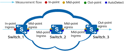
Automatic in-band flow measurement
- Author: Gu Suqin
- Updated on: 2021-10-28
- Views: 2713
- Average rating:


