What Is HVPN? Why Do We Need HVPN?
Hierarchy VPN (HVPN) is a VPN technology applied to hierarchical networks. Conventional BGP/MPLS IP VPN adopts a flat network model and requires all provider edges (PEs) to have the same performance. If the performance of some PEs is not so high, the performance of the entire network is affected, limiting the number of access users. To solve this problem, HVPN converts the flat network model into a hierarchical network model to lower the requirements on device performance level by level, improve network scalability, and facilitate the planning and design of large-scale networks.
Why Do We Need HVPN?
Background of HVPN
A BGP/MPLS IP VPN adopts a flat network model. It uses the Border Gateway Protocol (BGP) to advertise VPN routes and Multiprotocol Label Switching (MPLS) to forward VPN packets on the service provider's backbone network. On the network shown in the following figure, PEs refer to edge devices on the service provider network. All PEs are on the same plane.
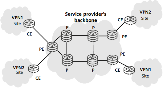
BGP/MPLS IP VPN model
On a BGP/MPLS IP VPN, the pressure of VPN service deployment is concentrated on PEs, which are all required to deliver the same level of performance. As the network grows in both scale and service diversity, the access capabilities of some PEs fail to meet requirements. On a flat network, the performance issues of some PEs may affect the performance and scalability of the entire network, which is not conducive to large-scale VPN deployment. Moreover, hierarchical architectures are currently used in most networking design scenarios. For example, metro networks typically use a three-layer architecture consisting of the access layer, aggregation layer, and core layer. To deploy VPN functions on a hierarchical network, hierarchy VPN (HVPN) is introduced.
To prevent the low performance levels of some PEs from affecting the performance of the entire network and limiting the number of access users, the BGP/MPLS IP VPN needs to shift from the flat model to the hierarchical model. In other words, HVPN needs to be deployed. On the network shown in the following figure, HVPN distributes PE functions across multiple PEs that play different roles.
HVPN Networking and Advantages
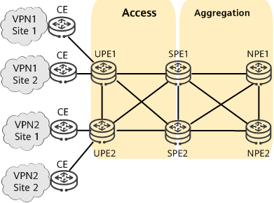
HVPN networking
Classification of Devices on an HVPN
Underlayer provider edge (UPE): a type of PE directly connected to users. A UPE is also referred to as a user-end PE and mainly provides access services for users.
Superstratum provider edge (SPE): a type of PE connected to UPEs and located on the core of a network. An SPE is also referred to as a service provider-end PE and manages and advertises VPN routes.
Network provider edge (NPE): a type of PE connected to SPEs and located on the network side. An NPE is also referred to as a network provider-end PE.
The functions of SPEs and UPEs reflect the characteristics of PEs at different levels. UPE and SPE roles are relative concepts. That is, in a hierarchical PE structure, an upper-level PE is the SPE relative to the lower level, and a lower-level PE is the UPE relative to the upper level.
Functions of Devices on an HVPN
- A UPE is mainly responsible for user access. It needs to maintain only the routes of directly connected VPN sites. The routes of remote VPN sites are represented by a default or summary route. A UPE assigns inner VPN labels to the routes of its directly connected sites, and uses MP-BGP to advertise the labels to the corresponding SPE along with VPN routes.
- An SPE mainly maintains and floods VPN routes. It maintains all VPN routes, including routes in the local and remote sites.
- An NPE mainly connects to SPEs to learn routes from UPEs.
A UPE and an SPE exchange packets based on labels and need to use only one interface for interconnection with each other. An SPE does not need to provide a large number of interfaces for user access. The interconnection interfaces between a UPE and an SPE can be physical interfaces, sub-interfaces (such as VLAN sub-interfaces), or tunnel interfaces (such as LSP interfaces). If there is an IP or MPLS network between a UPE and an SPE, the UPE and SPE can be connected through tunnel interfaces to exchange labeled packets over a tunnel. The requirements of SPEs and UPEs differ according to the roles they play on a network. Specifically, SPEs require large-capacity routing tables and high forwarding performance, but few interface resources. UPEs, in contrast, require only low-capacity routing tables and low forwarding performance, but high access capabilities.
HVPN fully utilizes network layering advantages, such as the high performance of upper-level devices and strong access capabilities of lower-level devices, to provide the functions of a PE. For this reason, this solution is also called hierarchy of PE/hierarchical provider edge (HoPE).
Advantages of HVPN Networking
- Provides high scalability. Lower-level PEs with insufficient performance can be moved downwards by adding upper-level PEs for them, while upper-level PEs with insufficient access capabilities can be moved further upwards by adding lower-level PEs for them.
- Conserves limited interface resources. The lower-level and upper-level PEs exchange traffic based on labels and need to use only one interface or sub-interface for interconnection with each other.
- Relieves the burden of lower-level PEs. A lower-level PE needs to maintain only local VPN routes. The remote VPN routes are represented by a default or summary route.
- Reduces configuration workloads. The upper-level and lower-level PEs exchange routes and advertise labels through the dynamic routing protocol MP-BGP. Each lower-level PE needs to establish only one MP-BGP peer relationship.
How Does HVPN Work?
The HVPN bearer solution, which is applicable to large-scale networks with dynamic routing capabilities, can reduce the pressure on top-level aggregation devices.
HVPN Modes
HVPN can be classified into HoVPN and H-VPN.
- HoVPN: SPEs advertise only default routes to UPEs. UPEs do not have specific routes to NPEs and can use only default routes to send VPN service data to SPEs, implementing route isolation. HoVPN allows devices with low route management capabilities to be used as UPEs, reducing network deployment costs.
- H-VPN: SPEs can advertise specific routes to UPEs. UPEs function as RR clients to receive specific routes reflected by SPEs (functioning as RRs), which facilitates route management and traffic forwarding control.
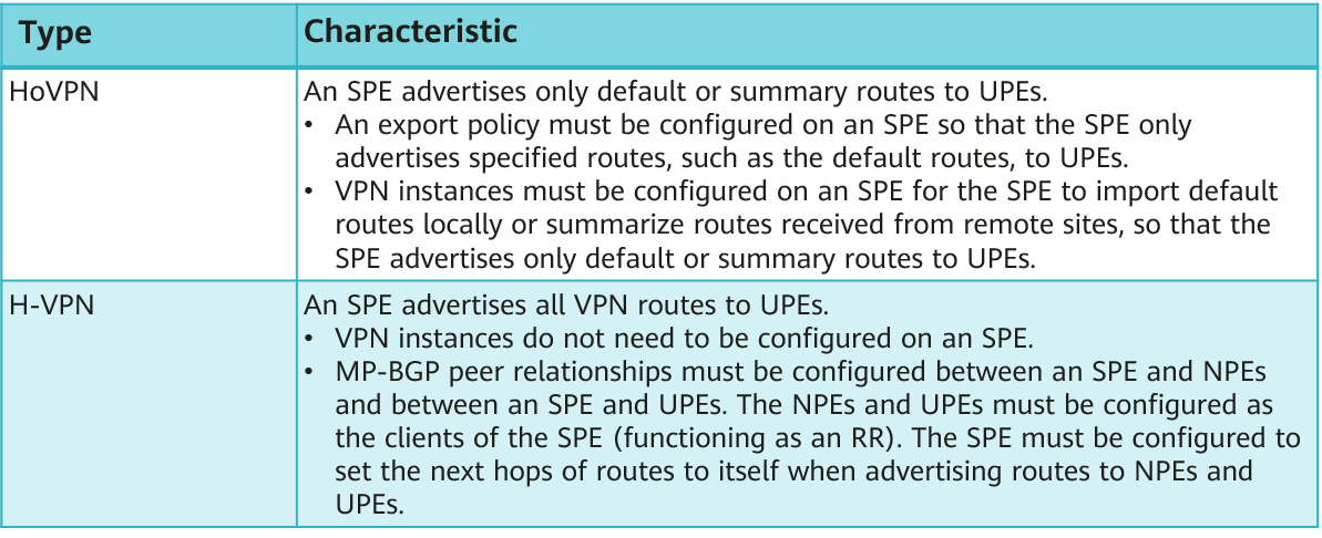
Comparison between HoVPN and H-VPN
Route Advertisement from CE1 to CE2 on an HoVPN or H-VPN
Route advertisement from CE1 to CE2 in HoVPN networking is similar to that in H-VPN networking. See the following figure.
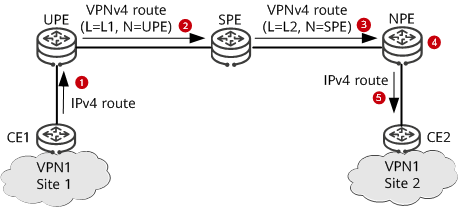
Route advertisement from CE1 to CE2 in HoVPN or H-VPN networking
CE1 advertises an IPv4 route to the UPE using a routing protocol.
The UPE applies for inner VPN label L1 for the received IPv4 route and converts the route to a VPNv4 route. Then, the UPE sets itself as the next hop of the route and advertises the route to the SPE together with label L1.
After receiving the labeled VPNv4 route, the SPE saves label L1 and applies for inner VPN label L2 for the VPNv4 route. Then, the SPE sets itself as the next hop of the route and advertises the route to the NPE together with label L2.
After receiving the labeled VPNv4 route, the NPE converts the route to an IPv4 route and imports the route to its VPN IPv4 routing table if the next hop of the route is reachable. The NPE retains inner VPN label L2 and recursive tunnel ID information of the route for later packet forwarding.
The NPE advertises the IPv4 route to CE2 using a routing protocol.
Route Advertisement from CE2 to CE1 on an HoVPN
The following figure shows route advertisement from CE2 to CE1 on an HoVPN.
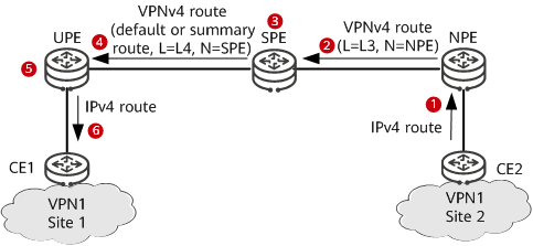
Route advertisement from CE2 to CE1 on an HoVPN
CE2 advertises an IPv4 route to the NPE using a routing protocol.
The NPE applies for inner VPN label L3 for the received IPv4 route and converts the route to a VPNv4 route. Then, the NPE sets itself as the next hop of the route and advertises the route to the SPE together with label L3.
After receiving the labeled VPNv4 route, the SPE saves label L3, converts the route to an IPv4 route, and imports the route to its VPN IPv4 routing table if the next hop of the route is reachable.
The SPE imports a default route or summary VPN route to its VPN IPv4 routing table and applies for label L4 for the route. Then, the SPE converts the default route or summary VPN route to a VPNv4 route, sets itself as the next hop of the VPNv4 route, and advertises the route to the UPE.
After receiving the labeled VPNv4 route, the UPE converts the route to an IPv4 route and imports the route to its VPN IPv4 routing table if the next hop of the route is reachable.
The UPE advertises the IPv4 route to CE1 using a routing protocol.
Route Advertisement from CE2 to CE1 on an H-VPN
The following figure shows route advertisement from CE2 to CE1 on an H-VPN.
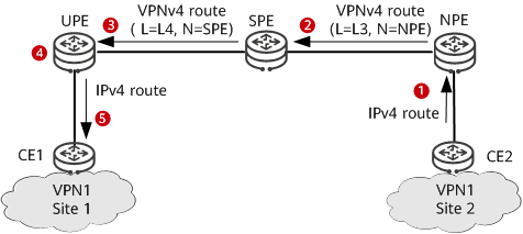
Route advertisement from CE2 to CE1 on an H-VPN
CE2 advertises an IPv4 route to the NPE using a routing protocol.
The NPE applies for inner VPN label L3 for the received IPv4 route and converts the route to a VPNv4 route. Then, the NPE sets itself as the next hop of the route and advertises the route to the SPE together with label L3.
After receiving the labeled VPNv4 route, the SPE saves label L3 and applies for inner VPN label L4 for the route. Then, the SPE sets itself as the next hop of the route and advertises the route to the UPE together with label L4.
After receiving the labeled VPNv4 route, the UPE converts the route to an IPv4 route and imports the route to its VPN IPv4 routing table if the next hop of the route is reachable.
The UPE advertises the IPv4 route to CE1 using a routing protocol.
Packet Forwarding from CE2 to CE1 on an HoVPN or H-VPN
The following figure shows packet forwarding from CE2 to CE1 on an HoVPN or H-VPN.
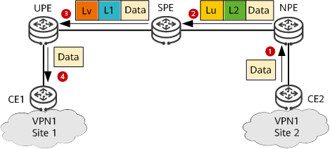
Packet forwarding from CE2 to CE1 on an HoVPN or H-VPN
CE2 sends a VPN packet to the NPE.
After receiving the packet, the NPE searches its VPN forwarding table for a tunnel to forward the packet based on the destination address of the packet. Then, the NPE adds an inner VPN label L2 and an outer tunnel label Lu to the packet and sends the packet to the SPE over the found tunnel.
After receiving the packet, the SPE replaces the outer tunnel label Lu with Lv and the inner VPN label with L1. Then, the SPE sends the packet to the UPE over the corresponding tunnel.
After receiving the packet, the UPE removes the outer tunnel label Lv, searches for a VPN instance corresponding to the packet based on the inner VPN label L1, and removes label L1 after the VPN instance is found. Then, the UPE searches the VPN forwarding table of this VPN instance for the outbound interface of the packet based on the destination address of the packet. Finally, the UPE sends the packet through this outbound interface to CE1. At this time, the packet is a native IP packet.
Packet Forwarding from CE1 to CE2 on an HoVPN
The following figure shows packet forwarding from CE1 to CE2 on an HoVPN.
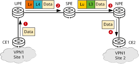
Packet forwarding from CE1 to CE2 on an HoVPN
CE1 sends a VPN packet to the UPE.
After receiving the packet, the UPE searches its VPN forwarding table for a tunnel to forward the packet based on the destination address of the packet (the UPE does so by matching the destination address of the packet against the forwarding entry for the default or summary route). Then, the UPE adds an inner VPN label L4 and an outer tunnel label Lv to the packet and sends the packet to the SPE over the found tunnel.
After receiving the packet, the SPE removes the outer tunnel label Lv, searches for the VPN instance corresponding to the packet based on the inner VPN label L4, and removes label L4 after the VPN instance is found. The SPE then searches the VPN forwarding table of this VPN instance for a tunnel to forward the packet based on the destination address of the packet. Finally, the SPE adds an inner VPN label L3 and an outer tunnel label Lu to the packet and sends the packet to the NPE over the found tunnel.
After receiving the packet, the NPE removes the outer tunnel label Lu, searches for a VPN instance corresponding to the packet based on the inner VPN label L3, and removes label L3 after the VPN instance is found. Then, the NPE searches the VPN forwarding table of this VPN instance for the outbound interface of the packet based on the destination address of the packet. Finally, the NPE sends the packet through this outbound interface to CE2. At this time, the packet is a native IP packet.
Packet Forwarding from CE1 to CE2 on an H-VPN
The following figure shows packet forwarding from CE1 to CE2 on an H-VPN.
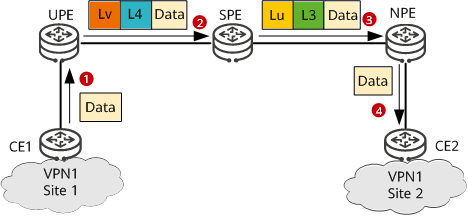
Packet forwarding from CE1 to CE2 on an H-VPN
CE1 sends a VPN packet to the UPE.
After receiving the packet, the UPE searches its VPN forwarding table for a tunnel to forward the packet based on the destination address of the packet (the UPE does so by matching the destination address of the packet against the forwarding entries for specific routes received from the SPE). Then, the UPE adds an inner VPN label L4 and an outer tunnel label Lv to the packet and sends the packet to the SPE over the found tunnel.
After receiving the packet, the SPE replaces the outer tunnel label Lv with Lu and swaps the inner VPN label with L3. Then, the SPE sends the packet to the NPE over the corresponding tunnel.
After receiving the packet, the NPE removes the outer tunnel label Lu, searches for a VPN instance corresponding to the packet based on the inner VPN label L3, and removes label L3 after the VPN instance is found. Then, the NPE searches the VPN forwarding table of this VPN instance for the outbound interface of the packet based on the destination address of the packet. Finally, the NPE sends the packet through this outbound interface to CE2. At this time, the packet is a native IP packet.
Typical Application Scenarios of HVPN
HVPN enables IP RANs to provide excellent fixed-mobile convergence (FMC) capabilities and simple, flexible networking.
Application of HVPN on an IP RAN
The IP RAN has characteristics such as diversified access modes, large network scale, and flexible service implementation mechanisms. Its overall architecture is hierarchical. From the core layer to the access layer, the requirements on device performance decrease, but the network scale increases. HVPN is widely used on IP RANs (usually at the aggregation and access layers) to isolate routes and faults. HVPN can also lower requirements on access devices.
HVPN uses hierarchical L3VPN to isolate faults, ensuring high reliability and security of the entire network.
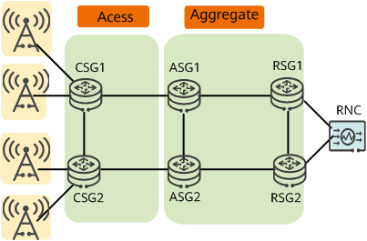
Application of HVPN on an IP RAN
On an IP RAN, PEs are classified into UPEs, SPEs, and NPEs by network layer (access, aggregation, and core layers). UPEs correspond to cell site gateways (CSGs), SPEs correspond to aggregation site gateways (ASGs), and NPEs correspond to radio service gateways (RSGs).
- CSG: On an HVPN, CSGs function as UPEs to provide access services for various base stations.
- ASG: On an HVPN, ASGs function as SPEs to provide access services for UPEs.
- RSG: On an HVPN, RSGs function as NPEs to connect to base station controllers (RNCs).
The HVPN bearer solution, which is applicable to large-scale networks with dynamic routing capabilities, can reduce the pressure on top-level aggregation devices.
Application of Inter-AS Seamless MPLS+HVPN on an IP RAN
Although the HVPN solution divides services into different layers based on device capabilities at different network layers, it is not flexible enough for service expansion.
To solve this problem, the HVPN solution is often used together with the seamless MPLS solution. The seamless MPLS solution uses E2E inter-AS LSPs to resolve the scalability issue of access point services. In addition to enabling communication between base stations and base station controllers, inter-AS seamless MPLS+HVPN takes advantage of reduced network construction costs offered by HVPN.
The following figure shows the inter-AS seamless MPLS+HVPN networking. The access and aggregation layers reside in AS 100, and the core layer resides in AS 200. Inter-AS seamless MPLS+HVPN is deployed to provide VPN services.
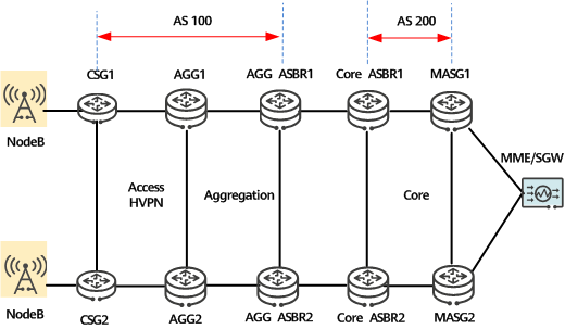
Inter-AS seamless MPLS+HVPN networking
The following uses mobile bearer services as an example. In the seamless MPLS+HVPN solution, HVPN is deployed between CSGs and AGGs, and inter-AS seamless MPLS is deployed between AGGs and mobile aggregate service gateways (MASGs). The AGGs hierarchically provide L3VPN services.
Seamless MPLS+HVPN combines the advantages of seamless MPLS and HVPN. Seamless MPLS allows any two nodes to transmit services across the access, aggregation, and core layers located in different ASs through an LSP, providing high service scalability. Moreover, HVPN enables carriers to save network deployment costs by deploying devices with layer-specific capacities to meet service requirements.
- Author: Huang Huixian
- Updated on: 2021-09-30
- Views: 13318
- Average rating:


