What Is IPSG?
IP Source Guard (IPSG) implements source IP address filtering based on Layer 2 interfaces. IPSG uses a binding table to maintain the mapping between information such as IP addresses and MAC addresses of hosts on the network. By comparing packet information with the binding table, IPSG prevents malicious hosts from using forged IP addresses to impersonate authorized users. In addition, IPSG prevents unauthorized hosts from accessing or attacking networks using forged IP addresses.
Why Do We Need IPSG?
As networks grow larger and bring more convenience, many attackers attempt to profit from the networks, greatly affecting network security. Some attackers forge IP addresses of authorized users to obtain network access rights and access networks. As a result, authorized users cannot access networks, and sensitive information may be intercepted. Source IP addresses are forged in such attacks, which are thereby called IP address spoofing attacks. IPSG can prevent such attacks by matching packets against a binding table.
- IPSG provides secure network environments and more stable network services.
- IPSG reduces costs for ensuring normal network operations and information security.
How Is IPSG Implemented?
IPSG Binding Tables
IPSG maintains a binding table that records the mapping between source IP addresses, source MAC addresses, VLANs, and inbound interfaces. When an IPSG-enabled Layer 2 interface receives IP packets, the interface matches the packet information against the binding table, and permits only packets for which a match is found.
Table 1 describes two types of binding tables: static and dynamic binding tables.
Type |
Generation Method |
Application Scenario |
|---|---|---|
Static binding table |
Manually configured |
A network with a few IPv4 hosts that use static IP addresses. |
Dynamic DHCP snooping binding table |
After DHCP snooping is configured, hosts request IP addresses from the DHCP server. The device dynamically generates DHCP snooping binding entries according to the DHCP reply packets returned by the DHCP server. |
A network with many IPv4 hosts that obtain IP addresses from the DHCP server. |
After the bind table is generated, the IPSG-enabled device delivers ACL rules to the specified interface or VLAN according to the binding table, and then checks all IP packets against the ACL rules. Only packets matching the ACL rules are allowed to pass through. When the binding table is modified, the device delivers the ACL rules again.
Typically, IPSG is configured on interfaces or in VLANs of a user-side access device.
- After IPSG is enabled on a user-side interface, it checks all IP packets received by the interface against binding entries.
- After IPSG is enabled in a user-side VLAN, it checks the IP packets received by all interfaces in the VLAN against binding entries.
- If the user-side access device does not support IPSG, you can configure IPSG on the interfaces or in VLANs of the upper-layer device.
IPSG Interface Roles
IPSG can be configured only on Layer 2 physical interfaces or in VLANs. It also checks the packets only on the untrusted interfaces with IPSG enabled and considers all interfaces to be untrusted by default (you can specify trusted interfaces). The trusted and untrusted interfaces in IPSG are the same as those used in DHCP snooping. In addition, these interfaces are also valid for IPSG based on a static binding table.
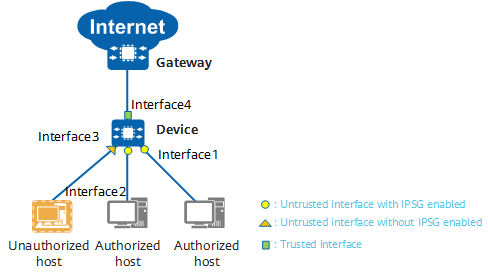
The following is an example of interface roles in IPSG:
- Interface1 and Interface2 are untrusted interfaces with IPSG enabled. The device performs an IPSG check on the packets received by these interfaces.
- Interface3 is an untrusted interface with IPSG disabled. The device does not perform an IPSG check on the packets received by this interface. Consequently, Interface3 is prone to attacks.
- Interface4 is a trusted interface specified by users. The device does not perform an IPSG check on the packets received by this interface; however, it is not prone to attacks.

IPSG interface roles
IPSG Filtering
A binding entry contains four items: IP address, MAC address, VLAN ID, and inbound interface. IPSG checks received packets against all items in a static binding entry. For entries in a dynamic binding table, you need to specify the items against which IPSG performs checks. Table 2 lists the common check methods.
Item |
Description |
|---|---|
Source IP address |
The device forwards only the packets whose source IP addresses match binding entries. |
Source MAC address |
The device forwards only the packets whose source MAC addresses match binding entries. |
Source IP address + source MAC address |
The device forwards only the packets whose source IP and MAC addresses match binding entries. |
Source IP address + source MAC address + interface |
The device forwards only the packets whose source IP addresses, source MAC addresses, and interfaces match binding entries. |
Source IP address + source MAC address + interface + VLAN |
The device forwards only the packets whose source IP addresses, source MAC addresses, interfaces, and VLANs match binding entries. |
IPSG Implementation
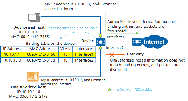
The following figure illustrates the implementation of IPSG. When an unauthorized host forges an authorized host's IP address to send packets to Device, Device discards these packets because they do not match binding entries.

IPSG implementation
Typical Applications of IPSG
IPSG Based on a Static Binding Table
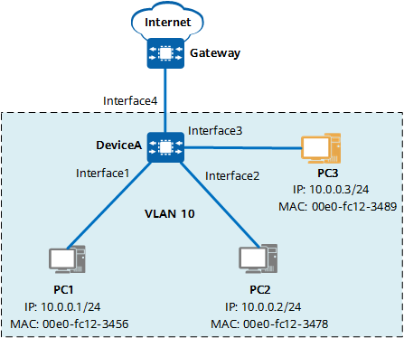
A static binding table needs to be manually created. Therefore, IPSG based on a static binding table is applicable to LANs that contain only a few hosts with fixed IP addresses. In the figure, the IP addresses, MAC addresses, VLAN IDs, and inbound interfaces of PC1 and PC2 are manually added to the IPSG binding table. All interfaces on DeviceA are added to VLAN 10, and IPSG is applied to VLAN 10. In this way, only the IP packets sent from PC1 and PC2 are allowed to be sent to the network through DeviceA, and other PCs cannot access the intranet even if they connect to idle interfaces.

Network diagram of IPSG based on a static binding table
IPSG Based on a Dynamic Binding Table
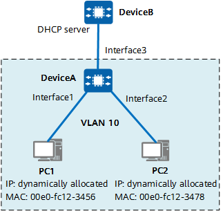
IPSG based on a dynamic binding table is applicable to LANs that contain many hosts or where hosts obtain IP addresses through DHCP. As shown in the figure, DHCP snooping is enabled for VLAN 10 on interfaces of DeviceA, and the interface connected to the DHCP server is configured as a trusted interface. Hosts can obtain IP addresses from an authorized DHCP server, and the IP addresses are mapped to the MAC addresses, VLAN IDs, and inbound interfaces of the hosts to form a dynamic DHCP snooping binding table. In this way, hosts configured with unauthorized static IP addresses cannot access the network.

Network diagram of IPSG based on a dynamic binding table
- Author: Zou Chun
- Updated on: 2024-02-27
- Views: 2981
- Average rating:


