What Is STP?
Spanning Tree Protocol (STP), defined in IEEE 802.1D, builds a loop-free logical topology for LANs. It blocks redundant links between any two network devices and leaves a single active link between them so as to eliminate loops. If an active link fails, STP immediately selects a proper redundant link and places it in forwarding state to ensure network connectivity.
Why Do We Need STP?
Devices on a LAN are often interconnected using redundant links to improve service resilience. This configuration, however, is prone to loops. Loops can easily cause broadcast storms, which can consume sufficient network resources so as to break down the network. Loops can also cause MAC address flapping, damaging the MAC address entries.
This is where STP comes in. STP-capable devices exchange information with one another to discover loops on the network, and then block some redundant links to trim the ring network into a loop-free tree network. This prevents packets from being infinitely replicated or propagated on the network, and protects device performance from being deteriorated by repeated packets.
STP vs. RSTP vs. MSTP
STP can fall into two meanings:
- In a narrow sense, STP refers to the STP protocol defined in IEEE 802.1D.
- In a broad sense, STP refers to the STP protocol defined in IEEE 802.1D, Rapid Spanning Tree Protocol (RSTP) defined in IEEE 802.1w, and Multiple Spanning Tree Protocol (MSTP) defined in IEEE 802.1s.
To elaborate, STP, RSTP, and MSTP provide the following capabilities:
- STP, a management protocol at the data link layer, is used to detect and prevent loops on a Layer 2 network. It, however, converges the network topology slowly.
- RSTP, an enhancement to STP, allows for rapid network topology convergence. However, both RSTP and STP have a defect, that is, all the VLANs on the same LAN share the same spanning tree. As a result, redundant links cannot be blocked by VLAN, and packets of all VLANs are forwarded alongside the same spanning tree.
- MSTP defines a virtual VLAN mapping table in which VLAN IDs are associated with spanning tree instances. Not only this, MSTP divides a switching network into multiple regions, each of which has multiple spanning tree instances that are mutually independent. Unlike STP and RSTP, MSTP provides multiple redundant paths for data forwarding. In addition, it implements load balancing among VLANs.
MSTP is compatible with RSTP and STP, and RSTP is compatible with STP. Table 1-1 compares the three spanning tree protocols.
Spanning Tree Protocol |
Characteristics |
Application Scenario |
|---|---|---|
STP |
|
All VLANs share one spanning tree without having to differentiating the traffic of users or services. |
RSTP |
|
|
MSTP |
|
Traffic from different VLANs is forwarded through different spanning trees for load balancing. The spanning trees are independent of each other. In this situation, users or services are distinguished by VLANs. |
How Does STP Work?
Basic Concepts of STP
Three elements are involved in trimming a ring network into a loop-free tree network: root bridge, root port, and designated port.
Root bridge: There is only one root bridge on the entire STP network. The root bridge is the logical center, but not necessarily the physical center, of the network. Typically, the root bridge should have high performance and be located at a higher layer of the network. When the network topology changes, the root bridge will be re-elected accordingly.
Root port: The root port on an STP-capable device has the smallest path cost to the root bridge and is responsible for forwarding data to the root bridge. Among all STP-capable ports on a device, the port with the smallest root path cost is the root port. An STP-capable device has only one root port, and there is no root port on the root bridge.
Designated port: Table 1-2 describes the designated bridge and designated port.
Reference Object |
Designated Bridge |
Designated Port |
|---|---|---|
Device |
A device that is directly connected to the reference object and forwards configuration BPDUs to the reference object. |
The designated bridge's port that forwards configuration BPDUs to the reference object. |
LAN |
A device that forwards configuration BPDUs to the reference object. |
The designated bridge's port that forwards configuration BPDUs to the reference object. |
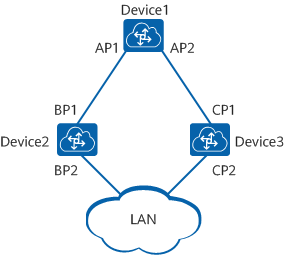
As shown in Figure 1-2, ports AP1 and AP2 reside on Device1, ports BP1 and BP2 reside on Device2, and ports CP1 and CP2 reside on Device3.
Device1 sends configuration BPDUs to Device2 through AP1. Device1 is the designated bridge of Device2, and AP1 is the designated port on Device1.
In addition, a device has a bridge ID (BID) and a port on the device has a port ID (PID). A PID is composed of a port priority and a port number. A BID is composed of a bridge priority and a bridge MAC address. On an STP network, the device with the smallest BID is elected as the root bridge.
STP Implementation
STP is implemented as follows:
- Select the root bridge: During network initialization, every STP-capable device considers itself the root bridge and sets the root bridge ID to its own BID. These devices then exchange configuration BPDUs and compare their root bridge IDs to find the one with the smallest root bridge ID, which will become the root bridge. All the ports on the root bridge are in Forwarding state.
- Select the root port: A device that is not elected as the root bridge selects the port that receives the optimal configuration BPDU as the root port. The root port is in Forwarding state.
- Select the designated port: The device calculates and generates a configuration BPDU for each port based on the configuration BPDU on the root port and path cost of the root port. The device then compares the generated configuration BPDU with the configuration BPDU received on the port.
If the generated configuration BPDU is superior, the port is selected as the designated port and periodically sends the generated configuration BPDU.
If the port's own configuration BPDU is superior, the port retains its own configuration BPDU and is blocked. In this case, the port only receives configuration BPDUs, and does not send them or forward data.
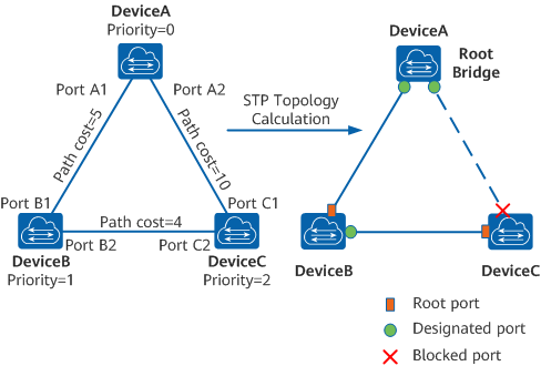
After the root bridge, root port, and designated ports are elected successfully, a tree topology is set up. When the topology is stable, only the root port and designated ports forward traffic. Other ports are in Blocking state; they only receive STP BPDUs and do not forward user traffic. The following example illustrates how STP calculation is implemented.
Initial status of each device
Table 1-3 shows the initial status of each device.
Table 1-3 Initial status of each deviceDevice
Port
Configuration BPDU
DeviceA
Port A1
{0, 0, 0, Port A1}
Port A2
{0, 0, 0, Port A2}
DeviceB
Port B1
{1, 0, 1, Port B1}
Port B2
{1, 0, 1, Port B2}
DeviceC
Port C1
{2, 0, 2, Port C1}
Port C2
{2, 0, 2, Port C2}
Topology calculation process and resulting configuration BPDUs
Table 1-4 shows the topology calculation process and resulting configuration BPDUs. The fields that are compared in a configuration BPDU include the root bridge ID, root path cost, sender BID, sender PID.
Table 1-4 STP topology calculation process and resulting configuration BPDUsDevice
Process
Resulting Configuration BPDU
DeviceA
- Port A1 receives the configuration BPDU {1, 0, 1, Port B1} from port B1 and finds it inferior to its own configuration BPDU {0, 0, 0, Port A1}, so port A1 discards the received configuration BPDU.
- Port A2 receives the configuration BPDU {2, 0, 2, Port C1} from port C1 and finds it inferior to its own configuration BPDU {0, 0, 0, Port A2}, so port A2 discards the received configuration BPDU.
- DeviceA finds that the root bridge and designated bridge specified in the configuration BPDUs on its ports are both itself. As such, DeviceA considers itself as the root bridge and periodically sends configuration BPDUs from each port without modifying the BPDUs.
- Port A1: {0, 0, 0, Port A1}
- Port A2: {0, 0, 0, Port A2}
DeviceB
- Port B1 receives the configuration BPDU {0, 0, 0, Port A1} from port A1 and finds it superior to its own configuration BPDU {1, 0, 1, Port B1}, so port B1 updates its configuration BPDU.
- Port B2 receives the configuration BPDU {2, 0, 2, Port C2} from port C2 and finds it inferior to its own configuration BPDU {1, 0, 1, Port B2}, so port B2 discards the received configuration BPDU.
- Port B1: {0, 0, 0, Port A1}
- Port B2: {1, 0, 1, Port B2}
- DeviceB compares the configuration BPDU on each port and finds that the configuration BPDU on port B1 is optimal. Port B1 then is elected as the root port and retains its own configuration BPDU.
- DeviceB calculates and generates the configuration BPDU {0, 5, 1, Port B2} for port B2 based on the configuration BPDU and path cost of the root port, and compares the generated configuration BPDU with the original configuration BPDU {1, 0, 1, Port B2} on port B2. The generated configuration BPDU is superior to the original one, so DeviceB selects port B2 as the designated port, replaces port B2's configuration BPDU with the generated one, and periodically sends the configuration BPDU from port B2.
- Root port (port B1): {0, 0, 0, Port A1}
- Designated port (port B2): {0, 5, 1, Port B2}
DeviceC
- Port C1 receives the configuration BPDU {0, 0, 0, Port A2} from port A2 and finds it superior to its own configuration BPDU {2, 0, 2, Port C1}, so port C1 updates its configuration BPDU.
- Port C2 receives the configuration BPDU {1, 0, 1, Port B2} from port B2 and finds it superior to its own configuration BPDU {2, 0, 2, Port C2}, so port C2 updates its configuration BPDU.
- Port C1: {0, 0, 0, Port A2}
- Port C2: {1, 0, 1, Port B2}
- DeviceC compares the configuration BPDU on each port and finds that the configuration BPDU on port C1 is optimal. Port C1 then is elected as the root port and retains its own configuration BPDU.
- DeviceC calculates and generates the configuration BPDU {0, 10, 2, Port C2} for port C2 based on the configuration BPDU and path cost of the root port, and compares the generated configuration BPDU with the original configuration BPDU {1, 0, 1, Port B2} on port C2. The generated configuration BPDU is superior to the original one, so DeviceC selects port C2 as the designated port and replaces its configuration BPDU with the generated one.
- Root port (port C1): {0, 0, 0, Port A2}
- Designated port (port C2): {0, 10, 2, Port C2}
- Port C2 receives the configuration BPDU {0, 5, 1, Port B2} from port B2 and finds it superior to its own configuration BPDU {0, 10, 2, Port C2}, so port C2 updates its configuration BPDU.
- Port C1 receives the configuration BPDU {0, 0, 0, Port A2} from port A2 and finds it to be the same as its own configuration BPDU, so port C1 discards the received configuration BPDU.
- Port C1: {0, 0, 0, Port A2}
- Port C2: {0, 5, 1, Port B2}
- The root path cost of port C1 is 10 (root path cost 0 in the received configuration BPDU plus the link path cost 10), and the root path cost of port C2 is 9 (root path cost 5 in the received configuration BPDU plus the link path cost 4). After comparing the root path costs of ports C1 and C2, DeviceC finds that port C2 has a smaller root path cost and therefore considers the configuration BPDU of port C2 superior to that of port C1. Port C2 then is elected as the root port and retains its own configuration BPDU.
- DeviceC calculates and generates the configuration BPDU {0, 9, 2, Port C1} for port C1 based on the configuration BPDU and path cost of the root port, and finds the calculated configuration BPDU inferior to the original configuration BPDU {0, 0, 0, Port A2} on port C1. DeviceC then blocks port C1 and does not update its configuration BPDU. In this manner, Port C1 no longer forwards data until spanning tree recalculation is triggered, for example, when the link between DeviceB and DeviceC goes down.
- Blocked port (port C1): {0, 0, 0, Port A2}
- Root port (port C2): {0, 5, 1, Port B2}
After the topology becomes stable, the root bridge still sends configuration BPDUs at intervals specified by the Hello timer. Each non-root bridge forwards the received configuration BPDUs through its designated port. When a non-root bridge receives a superior configuration BPDU on a port, it replaces the configuration BPDU on the port with the received configuration BPDU.
Typical Applications of STP
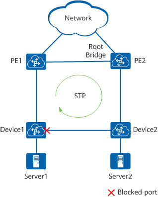
Devices on a complex network are most often interconnected using redundant links to improve service resilience. This configuration, however, is prone to loops. Loops can easily cause broadcast storms or MAC address flapping, deteriorating the network performance.
As shown in Figure 1-4, STP is deployed on the devices. These devices exchange information with one another to discover loops and block some ports, so as to trim the network into a loop-free tree network. This prevents packets from being infinitely replicated or propagated on the network, and protects device performance from being deteriorated by repeated packets.
- Author: Zhang Yanlin
- Updated on: 2021-09-30
- Views: 12667
- Average rating:


