What Is PCEP?
Path Computation Element Protocol (PCEP) is a TCP-based protocol defined by the Internet Engineering Task Force (IETF) path computation element (PCE) working group. It defines a set of messages and objects used to manage PCEP sessions and to request and send paths for inter-domain traffic engineering (TE) label switched paths (LSPs). PCEP provides a mechanism for a PCE to compute inter-domain LSPs for PCCs. PCEP interactions cover LSP state reporting from the PCCs to the PCE as well as the LSP delegation and optimization performed by the PCE.
Why Do We Need PCEP?
Path computation can be a complex task to complete, especially on large multi-domain networks. In some scenarios, it requires a special computation component to be deployed on the controller, and nodes in different domains need to collaborate with each other. This results in low path computation efficiency of nodes and also reduces their forwarding performance.
- PCE: a component that can compute constraint-compliant paths based on network topology information. The PCE can be deployed on a routing device or independent server. In most cases, however, it is integrated with a controller.
- Path computation client (PCC): a client application that requests the PCE to perform path computation. The PCC sends a path computation request to the PCE and receives the computation result from it. Because the PCC is typically integrated with a routing device, routing devices can be regarded as PCCs.
- PCEP: a protocol used for the communication between a PCE and PCC or between PCEs.
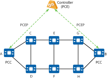
PCE architecture
PCEP offers the following benefits:
- Supports end-to-end optimal-path computation for services.
- Improves network bandwidth utilization and simplifies network deployment and maintenance.
- Supports centralized configuration and management of TE network topology information and tunnel constraints, simplifying network O&M.
What Are the Concepts Related to PCEP?
PCEP Messages
A PCC and PCE exchange PCEP messages to establish and maintain sessions, compute and update paths, and perform other operations. The following table lists different types of PCEP messages and their functions.
Message Type |
Function |
|---|---|
Open |
Used to establish a PCEP session and describe PCEP capabilities. |
Keepalive |
Used to carry PCEP session keepalive information in order to keep a PCEP session in the active state. |
PCReq |
Sent by a PCC to a PCE to request path computation. |
PCRep |
Sent by a PCE to a PCC in response to a path computation request from the PCC. |
PCRpt |
Sent by a PCC to a PCE to report the LSP state. |
PCUpd |
Sent by a PCE to a PCC to update LSP attributes. |
PCInitiate |
Sent by a PCE to a PCC to trigger path initialization. |
PCErr |
Used to notify a PCEP peer that a protocol error condition is met or a request is not compliant with PCEP specifications. |
PCNtf |
Sent by a PCE to a PCC to advertise the PCE state. |
Close |
Used to close a PCEP session. |
Each message may contain one or more objects describing specific functions.
How Does PCEP Work?
PCE discovery is first performed. After PCEs are discovered, the PCC establishes a PCEP session with the desired PCE to exchange information in client/server mode. In scenarios where TE tunnel establishment is triggered, the PCC (the ingress of the tunnel) sends a path computation request to the PCE and waits to receive the computation result from it. Unlike an IETF PCE, a Huawei PCE supports both manual verification and device-based automatic verification of the path computation result. If the computation result passes the verification, the PCE sends it to the PCC, which then establishes an LSP accordingly.
PCE Discovery
Before sending a path computation request, a PCC needs to discover an available PCE. Conversely, PCEs do not proactively discover the PCC, instead only passively performing path computation. The IP address of a PCE needs to be specified on the PCC, allowing the PCC to establish a connection with the PCE based on this address. You can configure multiple candidate PCEs for a PCC, which then selects one of them as the path computation server according to their priorities and source IP addresses. The candidate PCE with the highest priority is preferred. If the priorities of the candidate PCEs are the same, the one with the smallest source IP address is selected. In this case, the other candidate PCEs function as backups. If the path computation server fails, the PCC automatically selects another candidate PCE for path computation.
PCEP Sessions
A PCEP session needs to be established between a PCC and PCE, or between PCEs in different domains, so that the PCC and PCE or the PCEs in different domains can exchange information — including the path computation request and result — over this session.
The process of PCEP session establishment is as follows:
- A PCC initiates a TCP request to a PCE. After performing a three-way handshake, they establish a TCP connection.
- The PCC and PCE exchange PCEP Open messages to negotiate a session. Once the negotiation succeeds, they exchange PCEP Keepalive messages to acknowledge each other's session parameters and establish a session based on these parameters.
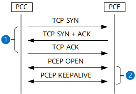
PCEP session establishment
The following figure shows the process of PCEP session maintenance. The PCC and PCE periodically send Keepalive messages to each other in order to maintain the PCEP session until it is closed. If one end does not receive the Keepalive message from the other end within a specified period, the session is considered to be down.
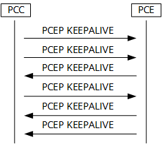
PCEP session maintenance
A PCEP session is terminated using a Close message, which can be initiated by either the PCC or PCE.
PCEP Applications
PCEP for MPLS TE
Path Computation
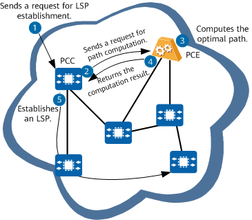
Intra-domain path computation
No. |
Description |
|---|---|
1 |
The PCC (ingress) is configured to request LSP establishment. |
2 |
The PCC sends a PCEP Report message to the PCE, requesting the PCE to perform LSP delegation and path computation. |
3 |
After receiving the Report message, the PCE saves the LSP information carried in the message to the LSP DB. It then performs path computation or global path optimization according to the TEDB and local policy. |
4 |
After verifying the computation result, the PCE sends an Update message carrying the result to the PCC. |
5 |
The PCC initiates RSVP signaling to establish a path according to the computation result. |
To further improve network bandwidth utilization and simplify network O&M, stateful PCE and LSP re-optimization as well as techniques used for centralized configuration and management of TE network information are introduced.
Stateful PCE and LSP Re-optimization
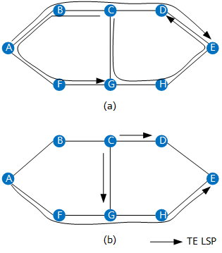
LSP establishment with and without stateful PCE
In this case, stateful PCE can be deployed to improve network bandwidth utilization. Stateful PCE constructs LSP DBs to monitor the LSP state (including bandwidth allocation and LSP establishment information) and computes globally optimal paths for the LSPs based on both LSP DB and TEDB information.
The preceding figure marked (b) shows three LSPs established after stateful PCE is deployed. As shown in the figure, the links between nodes A and B, B and C, and D and E all become available, thereby improving bandwidth utilization on the entire network.
- Active stateful PCE: The PCE proactively updates the states and parameters of delegated LSPs when computing a path for the reported LSP.
- Passive stateful PCE: The PCE only computes a path for the reported LSP, without proactively updating the states and parameters of delegated LSPs.
Centralized Configuration and Management of TE Network Information
Stateful PCE enables a PCE to centrally configure and manage the topology and tunnel attributes of a TE network, facilitating network management and maintenance. With this function enabled, a PCE uses the locally configured topology information and tunnel attributes to compute paths.
PCEP for SR-MPLS TE Policy
With the development of software-defined networking (SDN) and the emergence of Segment Routing (SR), PCEP has been extended to support SR, centralized SR-MPLS TE Policies in particular. SR provides the same explicit path selection capability as RSVP-TE but offers better scalability because it does not require transit nodes to maintain per-flow states. Given that transit nodes do not maintain states, SR does not support path computation on the headend based on bandwidth usage.
PCE-based SR can solve this problem. Because a PCE stores network-wide topology, TE, and path information, it can compute paths based on the resource usage of the entire network, improving network resource utilization.
Depending on the objects that send path computation requests, SR-MPLS TE Policies can be classified as follows in PCEP for SR-MPLS TE Policy scenarios:
- PCE-initiated SR-MPLS TE Policy: A PCE sends a PCInitiate message to a PCC (headend) to create an SR-MPLS TE Policy.
- PCC-initiated SR-MPLS TE Policy: A PCC (headend) sends an SR-MPLS TE Policy path computation request to a PCE, which then returns the path computation result to the PCC.
PCEP Extensions for SR-MPLS
PCEP extensions for SR-MPLS mainly include the new type PATH-SETUP-TYPE that supports SR-MPLS, the SR PCE Capabilities sub-TLV used to advertise SR-MPLS capabilities, and the SR-MPLS explicit route object (ERO) and SR-MPLS record route object (RRO) subobjects used to carry SR-MPLS SIDs. The following table expands on the details.
Category |
Name |
Function |
Carried In |
|---|---|---|---|
Type |
SR Path Setup Type (PST) |
Indicates the TE path created through SR-MPLS. |
PATH-SETUP-TYPE and PATH-SETUP-TYPE-CAPABILITIES TLVs |
Sub-TLV |
SR PCE Capabilities sub-TLV |
Advertises SR-MPLS capabilities. |
PATH-SETUP-TYPE-CAPABILITIES TLV |
Subobject |
SR-ERO subobject |
Carries information about the path computed by a PCE. |
ERO object |
SR-RRO subobject |
Carries information about the path on a PCC. |
RRO object |
Process of Creating a PCE-Initiated SR-MPLS TE Policy
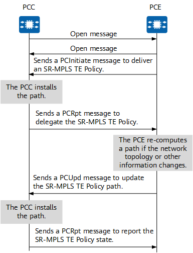
Basic process of creating a PCE-initiated SR-MPLS TE Policy
The detailed process is as follows:
- The PCC and PCE exchange Open messages to establish a PCEP session and negotiate supported capabilities. In addition, they use the SR PCE Capability sub-TLV to negotiate SR-MPLS capabilities for SR-MPLS TE Policy creation.
- The PCE sends a PCInitiate message to the PCC to create an SR-MPLS TE Policy, using the PCC as the headend.
- The PCE assigns a symbolic path name as a candidate path identifier of the SR-MPLS TE Policy in PCEP.
- If the PLSP-ID in the LSP object is set to 0, the PLSP-ID does not exist and the PCC needs to assign one.
- Attributes such as the SR-MPLS TE Policy ID, candidate path ID, and candidate path preference are carried in the Association object. All candidate paths of the SR-MPLS TE Policy belong to the same SR Policy association group.
- Path information is carried in the ERO. An SR-MPLS TE Policy uses the SR-ERO subobject to carry path information.
- After receiving the path information delivered by the PCE, the PCC performs path installation and applies for a PLSP-ID as a candidate path identifier.
- After the PCC completes path installation, it sends a PCRpt message to the PCE to report the SR-MPLS TE Policy state. In this message, the Delegate flag of the LSP object is set to 1, indicating that control over the SR-MPLS TE Policy has been delegated to the PCE. The Create flag in the LSP object is also set to 1, indicating that the PCC has created a PCE-initiated SR-MPLS TE Policy. The PLSP-ID is set to the unique value that the PCC has applied for locally. The SR-RRO subobject carries the path information of the SR-MPLS TE Policy.
- Because the PCC has delegated its control over the SR-MPLS TE Policy to the PCE, the PCE performs path re-computation if the network topology or other network information changes.
- The PCE sends a PCUpd message to deliver information about the recomputed path to the PCC and uses the PLSP-ID reported by the PCC as an identifier.
- After receiving the PCUpd message delivered by the PCE, the PCC updates the path.
- After the PCC completes path installation, it sends a PCRpt message to the PCE to report the SR-MPLS TE Policy state.
Process of Creating a PCC-Initiated SR-MPLS TE Policy in Stateless Bringup Mode
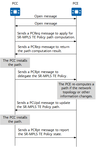
The detailed process is as follows:
- The PCC and PCE exchange Open messages to establish a PCEP session and negotiate supported capabilities. In addition, they use the SR PCE Capability sub-TLV to negotiate SR-MPLS capabilities for SR-MPLS TE Policy creation.
- The PCC sends a PCReq message to the PCE to apply for SR-MPLS TE Policy path computation.
- The PCE sends a PCRep message to the PCC to create an SR-MPLS TE Policy, using the PCC as the headend.
- The PCE assigns a symbolic path name as a candidate path identifier of the SR-MPLS TE Policy in PCEP.
- If the PLSP-ID in the LSP object is set to 0, the PLSP-ID does not exist and the PCC needs to assign one.
- Attributes such as the SR-MPLS TE Policy ID, candidate path ID, and candidate path preference are carried in the Association object. All candidate paths of the SR-MPLS TE Policy belong to the same SR Policy association group.
- Path information is carried in the ERO. An SR-MPLS TE Policy uses the SR-ERO subobject to carry path information.
- After receiving the path information delivered by the PCE, the PCC performs path installation and applies for a PLSP-ID as a candidate path identifier.
- After the PCC completes path installation, it sends a PCRpt message to the PCE to report the SR-MPLS TE Policy state. In this message, the Delegate flag of the LSP object is set to 1, indicating that control over the SR-MPLS TE Policy has been delegated to the PCE. The Create flag in the LSP object is also set to 1, indicating that the PCC has created a PCE-initiated SR-MPLS TE Policy. The PLSP-ID is set to the unique value that the PCC has applied for locally. The SR-RRO subobject carries the path information of the SR-MPLS TE Policy.
- Because the PCC has delegated its control over the SR-MPLS TE Policy to the PCE, the PCE performs path re-computation if the network topology or other network information changes.
- The PCE sends a PCUpd message to deliver information about the recomputed path to the PCC and uses the PLSP-ID reported by the PCC as an identifier.
- After receiving the PCUpd message delivered by the PCE, the PCC updates the path.
- After the PCC completes path installation, it sends a PCRpt message to the PCE to report the SR-MPLS TE Policy state.
Basic process of creating a PCC-initiated SR-MPLS TE Policy in stateless bringup mode
Process of Creating a PCC-Initiated SR-MPLS TE Policy in Stateful Bringup Mode
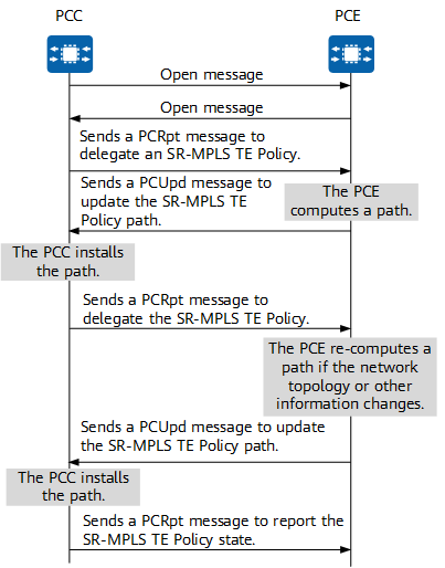
Basic process of creating a PCC-initiated SR-MPLS TE Policy in stateful bringup mode
The detailed process is as follows:
- The PCC and PCE exchange Open messages to establish a PCEP session and negotiate supported capabilities. In addition, they use the SR PCE Capability sub-TLV to negotiate SR-MPLS capabilities for SR-MPLS TE Policy creation.
- The PCC (headend) sends a PCRpt message to the PCE to delegate the SR-MPLS TE Policy.
- The PCC assigns a symbolic path name as a candidate path identifier of the SR-MPLS TE Policy in PCEP.
- The PCC assigns the PLSP-ID in the LSP object as a candidate path identifier of the SR-MPLS TE Policy in PCEP. The Delegate flag of the LSP object is set to 1, indicating that control over the SR-MPLS TE Policy has been delegated to the PCE.
- Attributes such as the SR-MPLS TE Policy ID, candidate path ID, and candidate path preference are carried in the Association object. All candidate paths of the SR-MPLS TE Policy belong to the same SR Policy association group.
- Path information is carried in the ERO. An SR-MPLS TE Policy uses the SR-ERO subobject to carry path information. An empty ERO is carried during delegation.
- After receiving the delegation message from the PCC, the PCE computes a path and delivers it to the PCC through a PCUpd message, using the PLSP-ID reported by the PCC as an identifier.
- After receiving the path information delivered by the PCE, the PCC performs path installation.
- After the PCC completes path installation, it sends a PCRpt message to the PCE to report the SR-MPLS TE Policy state. In this message, the Delegate flag of the LSP object is set to 1, indicating that control over the SR-MPLS TE Policy has been delegated to the PCE. The PLSP-ID is set to the unique value that the PCC has applied for locally. The SR-RRO subobject carries the path information of the SR-MPLS TE Policy.
- Because the PCC has delegated its control over the SR-MPLS TE Policy to the PCE, the PCE performs path re-computation if the network topology or other network information changes.
- The PCE sends a PCUpd message to deliver information about the recomputed path to the PCC and uses the PLSP-ID reported by the PCC as an identifier.
- After receiving the PCUpd message delivered by the PCE, the PCC updates the path.
- After the PCC completes path installation, it sends a PCRpt message to the PCE to report the SR-MPLS TE Policy state.
SR Policy Association Group
The SR Policy Association Group object is added to PCEP to carry SR-MPLS TE Policy information. It can carry five types of TLVs listed in the following table.
TLV Name |
Function |
|---|---|
SRPOLICY-POL-ID TLV |
Describes the identifier of an SR-MPLS TE Policy. This is a mandatory TLV for the SR Policy Association Group object, and only one SRPOLICY-POL-ID TLV can be carried. |
SRPOLICY-POL-NAME TLV |
Describes the name of an SR-MPLS TE Policy. This is an optional TLV for the SR Policy Association Group object, and only one SRPOLICY-POL-NAME TLV can be carried. |
SRPOLICY-CPATH-ID TLV |
Describes the identifier of an SR-MPLS TE Policy's candidate path. This is a mandatory TLV for the SR Policy Association Group object, and only one SRPOLICY-CPATH-ID TLV can be carried. |
SRPOLICY-CPATH-NAME TLV |
Describes the name of an SR-MPLS TE Policy's candidate path. This is an optional TLV for the SR Policy Association Group object, and only one SRPOLICY-CPATH-NAME TLV can be carried. |
SRPOLICY-CPATH-PREFERENCE TLV |
Describes the preference of an SR-MPLS TE Policy's candidate path. This is an optional TLV for the SR Policy Association Group object, and only one SRPOLICY-CPATH-PREFERENCE TLV can be carried. If the SRPOLICY-CPATH-PREFERENCE TLV is not carried, the preference of an SR-MPLS TE Policy's candidate path uses the default value 100. |
Automatic Bandwidth Adjustment
Automatic bandwidth adjustment enables an SR-MPLS TE Policy to automatically adjust bandwidth based on the traffic volume. Specifically, tunnel traffic is sampled at a fixed interval A (for example, 5 minutes) to obtain the maximum bandwidth of the traffic in an automatic bandwidth adjustment period B (for example, 24 hours). According to this obtained value, a PCC sends the requested bandwidth to a PCE (controller), which then re-computes an SR-MPLS TE Policy path accordingly and delivers it to the PCC.
PCEP for SRv6 TE Policy
PCEP has also been extended to support centralized SRv6 TE Policies. As mentioned earlier, SR provides the same explicit path selection capability as RSVP-TE but offers better scalability because it does not require transit nodes to maintain per-flow states. Given that transit nodes do not maintain states, SR does not support path computation on the headend based on bandwidth usage.
PCE-based SR can solve this problem. Because a PCE stores network-wide topology, TE, and path information, it can compute paths based on the resource usage of the entire network, improving network resource utilization.
Depending on the objects that send path computation requests, SRv6 TE Policies can be classified as follows in PCEP for SRv6 TE Policy scenarios:
- PCE-initiated SRv6 TE Policy: A PCE sends a PCInitiate message to a PCC (headend) to create an SRv6 TE Policy.
- PCC-initiated SRv6 TE Policy: SRv6 TE Policy configurations are delivered to a PCC (headend) through NETCONF, CLI, YANG, or another method.
PCEP Extensions for SRv6 TE Policy
PCEP extensions for SRv6 TE Policy mainly include three parts: the new type PATH-SETUP-TYPE of SRv6 TE Policy, the SRv6 PCE Capabilities sub-TLV used to advertise SRv6 capabilities, and the SRv6 ERO and SRv6 RRO subobjects used to carry SRv6 SIDs. The following table expands on the details.
Category |
Name |
Function |
Carried In |
|---|---|---|---|
Type |
SRv6 Path Setup Type (PST) |
Indicates the TE path created through SRv6. |
PATH-SETUP-TYPE and PATH-SETUP-TYPE-CAPABILITIES TLVs |
Sub-TLV |
SRv6 PCE Capabilities sub-TLV |
Advertises SRv6 capabilities. |
PATH-SETUP-TYPE-CAPABILITIES TLV |
Subobject |
SRv6-ERO subobject |
Carries information about the path computed by a PCE. |
ERO object |
SRv6-RRO subobject |
Carries information about the path on a PCC. |
RRO object |
Process of Creating a PCE-Initiated SRv6 TE Policy
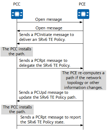
Basic process of creating a PCE-initiated SRv6 TE Policy
The detailed process is as follows:
- The PCC and PCE exchange Open messages to establish a PCEP session and negotiate supported capabilities. In addition, they use the SRv6 PCE Capability sub-TLV to negotiate SRv6 capabilities for SRv6 TE Policy creation.
- The PCE sends a PCInitiate message to the PCC to create an SRv6 TE Policy, using the PCC as the headend.
- The PCE assigns a symbolic path name as a candidate path identifier of the SRv6 TE Policy in PCEP.
- If the PLSP-ID in the LSP object is set to 0, the PLSP-ID does not exist and the PCC needs to assign one.
- Attributes such as the SRv6 TE Policy ID, candidate path ID, and candidate path preference are carried in the Association object. All candidate paths of the SRv6 TE Policy belong to the same SR Policy association group.
- Path information is carried in the ERO. An SRv6 TE Policy uses the SRv6-ERO subobject to carry path information.
- After receiving the path information delivered by the PCE, the PCC performs path installation and applies for a PLSP-ID as a candidate path identifier.
- After the PCC completes path installation, it sends a PCRpt message to the PCE to report the SRv6 TE Policy state. In this message, the Delegate flag of the LSP object is set to 1, indicating that control over the SRv6 TE Policy has been delegated to the PCE. The Create flag in the LSP object is also set to 1, indicating that the PCC has created a PCE-initiated SRv6 TE Policy. The PLSP-ID is set to the unique value that the PCC has applied for locally. The SRv6-RRO subobject carries the path information of the SRv6 TE Policy.
- Because the PCC has delegated its control over the SRv6 TE Policy to the PCE, the PCE performs path re-computation if the network topology or other network information changes.
- The PCE sends a PCUpd message to deliver information about the recomputed path to the PCC and uses the PLSP-ID reported by the PCC as an identifier.
- After receiving the PCUpd message delivered by the PCE, the PCC updates the path.
- After the PCC completes path installation, it sends a PCRpt message to the PCE to report the SRv6 TE Policy state.
SR Policy Association Group
The SR Policy Association Group object is added to PCEP to carry SRv6 TE Policy information. It can carry five types of TLVs listed in the following table.
TLV Name |
Function |
|---|---|
SRPOLICY-POL-ID TLV |
Describes the identifier of an SRv6 TE Policy. This is a mandatory TLV for the SR Policy Association Group object, and only one SRPOLICY-POL-ID TLV can be carried. |
SRPOLICY-POL-NAME TLV |
Describes the name of an SRv6 TE Policy. This is an optional TLV for the SR Policy Association Group object, and only one SRPOLICY-POL-NAME TLV can be carried. |
SRPOLICY-CPATH-ID TLV |
Describes the identifier of an SRv6 TE Policy's candidate path. This is a mandatory TLV for the SR Policy Association Group object, and only one SRPOLICY-CPATH-ID TLV can be carried. |
SRPOLICY-CPATH-NAME TLV |
Describes the name of an SRv6 TE Policy's candidate path. This is an optional TLV for the SR Policy Association Group object, and only one SRPOLICY-CPATH-NAME TLV can be carried. |
SRPOLICY-CPATH-PREFERENCE TLV |
Describes the preference of an SRv6 TE Policy's candidate path. This is an optional TLV for the SR Policy Association Group object, and only one SRPOLICY-CPATH-PREFERENCE TLV can be carried. If the SRPOLICY-CPATH-PREFERENCE TLV is not carried, the preference of an SRv6 TE Policy's candidate path uses the default value 100. |
- Author: Peng Lili
- Updated on: 2023-06-28
- Views: 3143
- Average rating:


