What Is Adaptive Routing?
Adaptive routing is a technology that dynamically determines routes based on the network topology and traffic load changes. By proactively detecting the link congestion status, adaptive routing preferentially selects a short and non-congested packet forwarding path to improve network throughput and resilience, as well as reduce network latency. Currently, adaptive routing and the direct topology are used together in large supercomputing centers.
Why Do We Need Adaptive Routing?
Building a large supercomputing center requires interconnection between a large number of compute nodes. However, expanding the cluster scale increases the network latency and deployment costs, failing to meet requirements regarding computing power and deployment. A direct topology features large-scale access and a small network diameter. In such a topology, adaptive routing can be deployed to achieve the following: When network links are normal, the shortest path is preferentially selected to forward packets. When the shortest path is congested, a non-shortest path that is not congested is selected to forward packets. In this way, network links are fully utilized to improve bandwidth utilization, meeting the requirements of high throughput, low latency, and low costs while supporting large-scale networking.
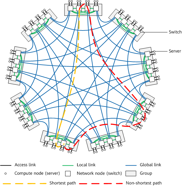
Adaptive routing in a direct topology
What Is a Dragonfly Topology?
Each network node in a direct topology is directly connected to a compute node, and no network device is specially used to interconnect network nodes. That is, in a direct topology, all devices are leaf nodes; there are no spine nodes typical of a traditional topology. The dragonfly topology is the most widely used direct topology. In the dragonfly topology, there are multiple groups, with full-mesh connections established between groups and within a group. This means each pair of groups are connected through one or more links; each network node in a group is directly connected to other network nodes in the group and can also be connected to other groups and compute nodes.
Each network node can support the following link types simultaneously:
- Global link: also called an inter-group link, connects nodes in different groups. A node's port, when connected to a global link, is called a global port.
- Local link: also called an intra-group link, connects nodes in the same group. A node's port, when connected to a local link, is called a local port.
- Access link: connects network nodes and compute nodes. A node's port, when connected to an access link, is called an access port.
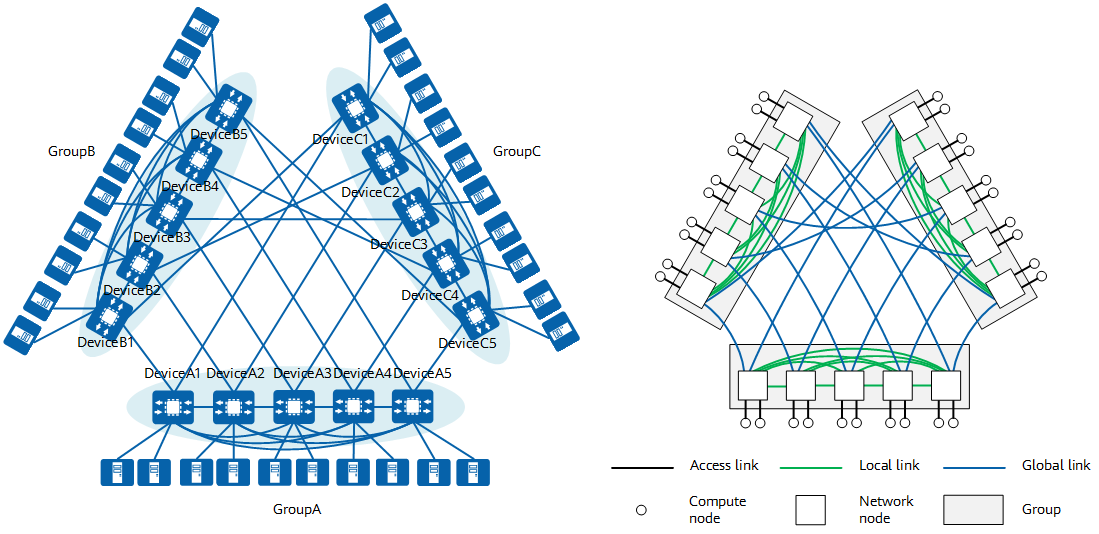
Comparison between adaptive routing networking and topology
In the dragonfly topology, the sum of bandwidths between each network node and other network nodes in the same group is represented by a, the sum of bandwidths between each network node and compute nodes is represented by p, and the sum of bandwidths between each network node and other groups is represented by h. To achieve better load balancing, it is recommended that the following condition be met: a = 2p = 2h. If other values are used, the following conditions must be met: a ≥2h and 2p ≥ 2h. To ensure better network performance, it is recommended that device interfaces be fully used. The link planning suggestions for networks of different scales are as follows:
- Small-scale networking: Each network node in a group is connected to all the other groups through multiple parallel links.
- Medium-scale networking: Each network node in a group is connected to all the other groups through one link.
- Large-scale networking: Each pair of groups is connected through one link.
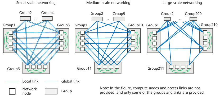
Dragonfly networking scenarios
How Does Adaptive Routing Work?
Each node on the network has multiple forwarding paths available for selection. However, only the ingress node (ingress network node of packets) uses the adaptive routing algorithm to select the optimal packet forwarding path. Subsequent non-ingress nodes forward packets by looking up the routing table, without needing to reselect a path.
Three routing tables are maintained on each network node: a public network routing table (maintains the routing information of the shortest path), a routing table of a Non-min VPN instance (maintains the routing information of the non-shortest paths), and a routing table of a Mix VPN instance (maintains the routing information of both the shortest and non-shortest paths). For the packets received on an access port, the shortest path or non-shortest path needs to be selected according to the adaptive routing algorithm. Therefore, the routing information needs to be searched in the routing table of a Mix VPN instance. For packets received on a min sub-interface of a global port or local port, the routing information of the shortest path needs to be searched in the public network routing table. For packets received on a non-min sub-interface of a local port, the routing information of the non-shortest path needs to be searched in the routing table of a Non-min VPN instance.
The packet forwarding process can be divided into two phases:
- The ingress node searches the best path table for the optimal packet forwarding path, determining the local outbound interface of the packets.
- A non-ingress node searches its routing table for the outbound interface of the packets based on the inbound interface of the packets.
How Does an Ingress Node Select the Optimal Path?
Based on node routing information and link congestion status, each network node maintains a best path table to store information about the optimal forwarding path. Using a destination IP address as an example, if the shortest path is not congested, information about the shortest path destined for the IP address is stored in the best path table; otherwise, information about the non-shortest paths destined for the IP address is stored.
Path selection on the ingress node in an intra-group communication scenario
The following figure shows the process of switching between the intra-group shortest and non-shortest paths in an intra-group communication scenario where compute node S sends packets to compute node D.
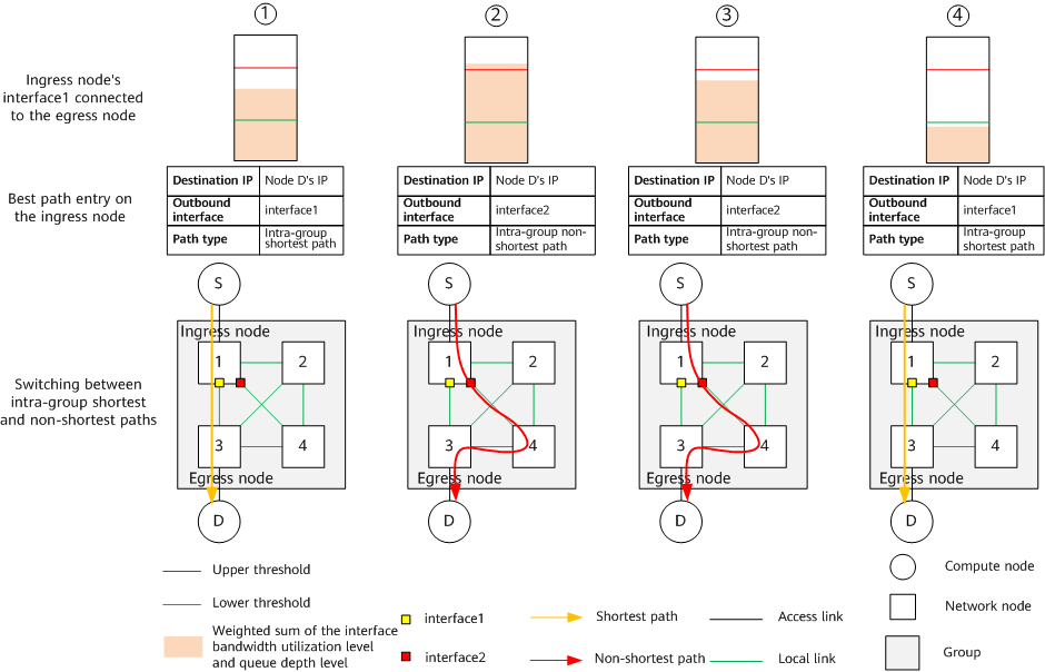
Switching between the intra-group shortest and non-shortest paths
- The intra-group shortest path along which compute node S sends packets to compute node D is S -> 1 -> 3 -> D, and the outbound interface interface1 of ingress node 1 on this path is not congested. Therefore, when receiving the packets sent by node S to node D, ingress node 1 searches the best path table and finds that the optimal forwarding path is the intra-group shortest path and the outbound interface is interface1. According to the search result in the best path table, ingress node 1 sends the packets to a non-ingress node through interface1.
- Interface1 of ingress node 1 is congested (the weighted sum of the bandwidth utilization level and queue depth level is higher than the sum of their upper thresholds). In this case, the shortest path passing through interface1 in the best path table is deleted and replaced with an intra-group non-shortest path. When receiving packets sent from node S to node D, ingress node 1 searches the best path table and finds that the optimal forwarding path is an intra-group non-shortest path and the outbound interface is interface2. According to the search result in the best path table, ingress node 1 sends the packets to a non-ingress node through interface2.
- The weighted sum of the bandwidth utilization level and queue depth level of interface1 falls below the sum of their upper thresholds. In this case, the optimal forwarding path stored in the best path table is still the intra-group non-shortest path. When receiving packets sent from node S to node D, ingress node 1 searches the best path table and finds that the optimal forwarding path is an intra-group non-shortest path and the outbound interface is interface2. According to the search result in the best path table, ingress node 1 sends the packets to a non-ingress node through interface2.
- The weighted sum of the bandwidth utilization level and queue depth level of interface1 falls below the sum of their lower thresholds. In this case, the optimal forwarding path stored in the best path table is changed to the intra-group shortest path. When receiving packets sent from node S to node D, ingress node 1 searches the best path table and finds that the optimal forwarding path is the intra-group shortest path and the outbound interface is interface1. According to the search result in the best path table, ingress node 1 sends the packets to a non-ingress node through interface1.
Path selection on the ingress node in an inter-group communication scenario
The following figure shows the process of switching between the inter-group shortest and non-shortest paths in an inter-group communication scenario where compute node S sends packets to compute node D.
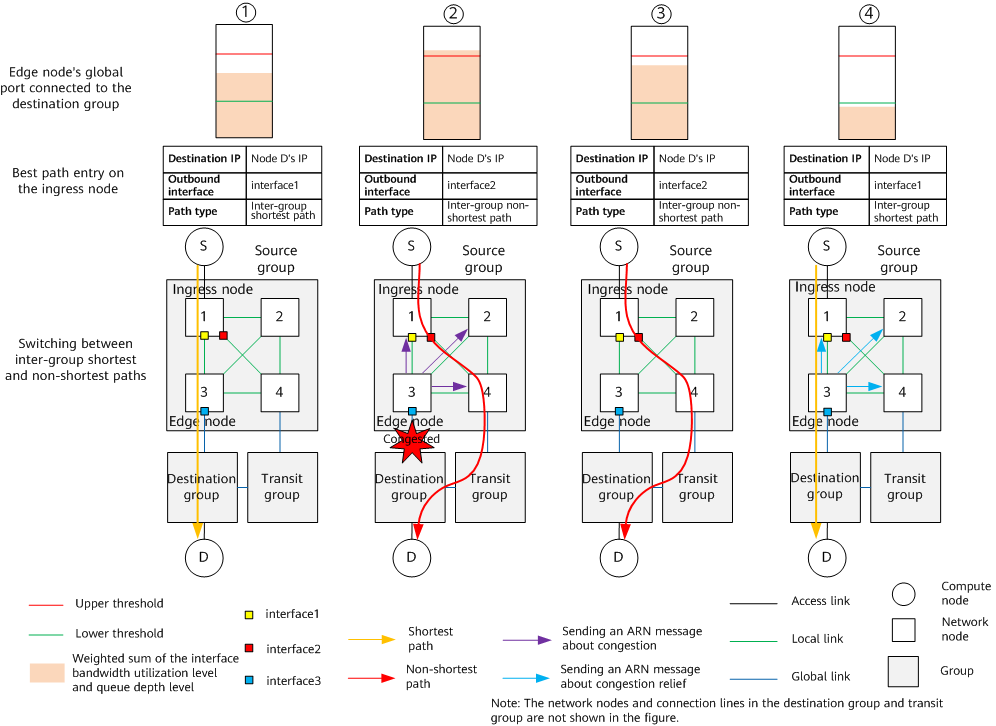
Switching between the inter-group shortest and non-shortest paths
- The inter-group shortest path along which compute node S sends packets to compute node D is source group -> interface3 of edge node 3 -> destination group, and interface3 is not congested. Therefore, when receiving the packets sent by node S to node D, ingress node 1 searches the best path table and finds that the optimal forwarding path is the inter-group shortest path and the outbound interface is interface1. According to the search result in the best path table, ingress node 1 sends the packets to a non-ingress node through interface1.
- Interface3 of edge node 3 is congested (the weighted sum of the bandwidth utilization level and queue depth level of interface3 is higher than the sum of their upper thresholds). In this case, edge node 3 sends an ARN message about congestion to other network nodes in the same group. After receiving this message, node 1 deletes the inter-group shortest path passing through interface3 from the best path table and replaces it with an inter-group non-shortest path. When receiving packets sent from node S to node D, ingress node 1 searches the best path table and finds that the optimal forwarding path is an inter-group non-shortest path and the outbound interface is interface2. According to the search result in the best path table, ingress node 1 sends the packets to a non-ingress node through interface2.
- The weighted sum of the bandwidth utilization level and queue depth level of interface3 falls below the sum of their upper thresholds. In this case, edge node 3 stops sending the ARN message about congestion to other network nodes in the same group, and the optimal forwarding path stored in the best path table of node 1 is still an inter-group non-shortest path. When receiving packets sent from node S to node D, ingress node 1 searches the best path table and finds that the optimal forwarding path is an inter-group non-shortest path and the outbound interface is interface2. According to the search result in the best path table, ingress node 1 sends the packets to a non-ingress node through interface2.
- The weighted sum of the bandwidth utilization level and queue depth level of interface3 falls below the sum of their lower thresholds. In this case, edge node 3 sends an ARN message about congestion relief to other network nodes in the same group. After receiving this message, node 1 changes the optimal forwarding path destined for node D in the best path table to the inter-group shortest path. When receiving packets sent from node S to node D, ingress node 1 searches the best path table and finds that the optimal forwarding path is the inter-group shortest path and the outbound interface is interface1. According to the search result in the best path table, ingress node 1 sends the packets to a non-ingress node through interface1.
How Does a Non-Ingress Node Forward Packets?
Packet forwarding of non-ingress nodes depends on the routing table maintained by each network node. Each local port has two Layer 3 sub-interfaces: min sub-interface and non-min sub-interface. The min sub-interface is used to forward packets along the shortest path, the non-min sub-interface is used to forward packets along the non-shortest path.
The packet forwarding rules on a non-ingress node are as follows:
- Receiving packets on a global port: The node searches the public network routing table for packet forwarding.
- Receiving packets on a min sub-interface of a local port: The node searches the public network routing table for packet forwarding.
- Receiving packets on a non-min sub-interface of a local port: The node searches the routing table of the Non-min VPN instance for packet forwarding.
- Author: Feng Yuanyuan
- Updated on: 2024-02-27
- Views: 2820
- Average rating:


