What Is IS-IS?
IS-IS is a dynamic routing protocol initially designed by the International Organization for Standardization (ISO) for its Connectionless Network Protocol (CLNP). To support IP routing, the Internet Engineering Task Force (IETF) extends and modifies IS-IS in relevant standards, which enables IS-IS to be applied to both TCP/IP and Open System Interconnection (OSI) environments. The new type of IS-IS is called Integrated IS-IS or Dual IS-IS. IS-IS uses the SPF algorithm to calculate routes. It is characterized by fast convergence and high scalability. Running at the data link layer, IS-IS has strong anti-attack capabilities and can implement interworking on large-scale networks.
Why Do We Need IS-IS?
Before the emergence of IS-IS, the Routing Information Protocol (RIP) was the most widely used IGP. RIP is a distance-vector routing protocol, which is gradually being replaced with IS-IS, due to the former's slow convergence, tendency to form routing loops, and poor scalability. IS-IS has the following advantages:
- IS-IS packets use the TLV format, which features high scalability.
- A router can be configured with multiple area addresses, making smooth combination of multiple areas possible.
- The packet structure is simple, ensuring high neighbor interaction efficiency.
- IS-IS works at the data link layer, independent of IP addresses.
- It uses the SPF algorithm, ensuring fast convergence.
- It applies to large networks, such as Internet service provider (ISP) networks.
What Are the Basic Concepts of IS-IS?
IS-IS Router Types
To support large-scale routing networks, IS-IS adopts a two-level structure in a routing domain. A large domain can be divided into multiple areas. Three levels of routing devices may exist on an IS-IS network. Generally, Level-1 routing devices are deployed within an area, Level-2 routing devices are deployed between areas, and Level-1-2 routing devices are deployed between Level-1 and Level-2 routing devices. The following figure shows a typical IS-IS network, on which the backbone area covers all Level-2 routing devices in area 1 and Level-1-2 routing devices in other areas.
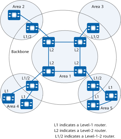
IS-IS topology
Level-1 router
A Level-1 router manages intra-area routing. It establishes neighbor relationships only with other Level-1 devices and Level-1-2 routers in the same area, and maintains only a Level-1 link state database (LSDB) which contains routing information specific to the local area. For packets destined for other areas, each Level-1 router forwards them to the nearest Level-1-2 router.
Level-2 router
A Level-2 router manages inter-area routing. It can establish neighbor relationships with other Level-2 routers and with Level-1-2 routing devices in other areas and maintains a Level-2 LSDB, which contains inter-area routing information.
All Level-2 routers form the backbone network of the routing domain. They are responsible for communications between areas. The Level-2 routers in the routing domain must be in succession to ensure the continuity of the backbone network. Only Level-2 routers can exchange data packets or routing information with routers outside the local area.
- Level-1-2 router
A router that belongs to both a Level-1 area and a Level-2 area is called a Level-1-2 router. It can establish Level-1 neighbor relationships with Level-1 and Level-1-2 routers in the same area. It can also establish Level-2 neighbor relationships with Level-2 and Level-1-2 routers in other areas. Level-1 devices can be connected to other areas only through Level-1-2 devices.
A Level-1-2 router maintains two LSDBs: a Level-1 LSDB and a Level-2 LSDB. The Level-1 LSDB is used for intra-area routing and the Level-2 LSDB is used for inter-area routing.
Relationships Between IS-IS Network Types and Network Links
IS-IS can run on broadcast links and Point-to-Point (P2P) links. Broadcast links include Ethernet and token ring links. P2P links include Point-to-Point Protocol (PPP) links.
IS-IS networks are classified into broadcast networks and P2P networks, as shown in the following figure. The network type of a broadcast link can be set to broadcast or P2P, whereas the network type of a P2P link can be set only to P2P.
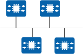
Broadcast network type

P2P network type
IS-IS Packet Types
IS-IS packets are classified into Hello protocol data units (PDUs), link state PDUs (LSPs), and sequence number PDUs (SNPs).
Hello PDU
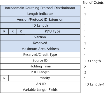
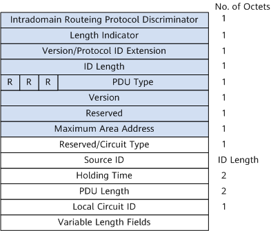
Hello packets, also called IS-to-IS Hello PDUs (IIHs), are used to set up and maintain neighbor relationships. On a broadcast network, Level-1 IS-IS uses Level-1 LAN IIHs; on a broadcast network, Level-2 IS-IS uses Level-2 LAN IIHs; on a non-broadcast network, P2P IIHs are used. IIHs on networks of different types have different formats. Compared to a LAN IIH, a P2P IIH does not have the Priority and LAN ID fields, but has a Local Circuit ID field. The Priority field indicates the DIS priority on a broadcast network, the LAN ID field indicates the system ID of the DIS and pseudonode, and the Local Circuit ID indicates the local link ID.
- Hello packets on a broadcast network: The following figure shows the format of a Hello packet on a broadcast network.
Level-1/Level-2 LAN IIH format - Hello packets on a P2P network: The following figure shows the format of Hello packets on a P2P network.
P2P IIH format
- Intradomain Routing Protocol Discriminator: network layer protocol identifier. In IS-IS, the value of this field is always 0x83.
- Length Indicator: length of the fixed header.
- ID Length: length of a system ID.
- PDU Type: PDU type.
- Maximum Area Address: maximum number of area addresses supported by an IS-IS area. Currently, this field has a fixed value of 0, indicating that a maximum of three area addresses are supported.
- TLV: Type/Length/Value. The TLVs contained in PDUs of different types are different.
LSP
LSPs are used to exchange link-state information. LSPs are classified into two types: Level-1 LSPs and Level-2 LSPs. Level-1 IS-IS transmits Level-1 LSPs. Level-2 IS-IS transmits Level-2 LSPs. Level-1-2 IS-IS can transmit both Level-1 and Level-2 LSPs.
The two types of LSPs have the same format, as shown in the following figure.
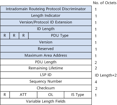
Level-1 or Level-2 LSP
The main fields are described as follows:
ATT: Attached bit
It is generated by a Level-1-2 router to indicate whether the originating router is connected to other areas. When a Level-1 router receives a Level-1 LSP with the ATT bit set from a Level-1-2 router, the Level-1 router creates a default route to the Level-1-2 router so that data can be routed to other areas.
Although the ATT bit is defined in both Level-1 and Level-2 LSPs, it is set only in Level-1 LSPs and only Level-1-2 routers can set this field.
OL: LSDB overload bit
Although the LSPs with the overload bit set are still flooded on the network, they are not used to calculate the routes that pass through the overloaded router. That is, after the overload bit is set on a router, other routers ignore the router when performing SPF calculation except for the direct routes of the router.
IS Type: type of the IS-IS generating the LSP
It is used to specify whether the IS-IS type is Level-1 or Level-2 (01 indicates Level-1 and 11 indicates Level-2).
SNP
Sequence Number PDUs (SNPs) describe summaries of all or some LSPs to synchronize LSDBs. SNPs are classified as Complete Sequence Number Protocol Data Units (CSNPs) or Partial Sequence Number Protocol Data Units (PSNPs). A CSNP contains summaries of all LSPs in an LSDB, which ensures LSDB synchronization between neighboring routing devices.
The way that SNPs are used on broadcast network links is different from that on P2P links.
- On broadcast network links, CSNPs are sent periodically by the DIS. If a neighbor finds that its LSDB is not synchronized, the neighbor sends PSNPs to request missing LSPs.
- On a P2P link, CSNPs are sent only during initial establishment of neighbor relationships. If a request is acknowledged, a neighbor sends a PSNP in response to a CSNP. If a neighbor finds that its LSDB is not synchronized, the neighbor sends PSNPs to request missing LSPs.
How Is an IS-IS Neighbor Relationship Established?
Neighbor Relationship Establishment
Two IS-IS routing devices must establish a neighbor relationship before exchanging protocol packets to implement routing. The way to establish an IS-IS neighbor relationship varies according to the network type.
Establishment of a neighbor relationship on a broadcast link
The following figure demonstrates the process of establishing a neighbor relationship between Level-2 routing devices on a broadcast link. The process of establishing a neighbor relationship between Level-1 routing devices on a broadcast network is similar to the process in this example.
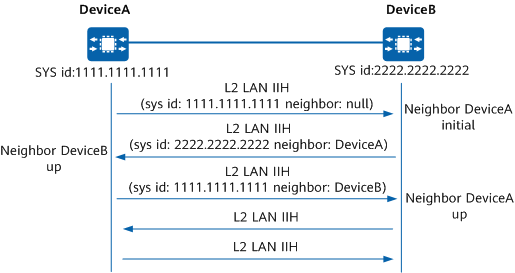
Process of establishing a neighbor relationship on a broadcast link
- DeviceA broadcasts a Level-2 LAN IIH without a neighbor identifier.
- After receiving the packet, DeviceB sets the state of the neighbor relationship between itself and DeviceA to Initial. Then, DeviceB replies DeviceA with a Level-2 LAN IIH, in which DeviceA is labeled as a neighbor of DeviceB.
- After receiving the packet, DeviceA sets the state of the neighbor relationship with DeviceB to Up. Then, DeviceA sends DeviceB a Level-2 LAN IIH, in which DeviceB is labeled as a neighbor of DeviceA.
- After receiving the packet, DeviceB sets the state of the neighbor relationship with DeviceA to Up. In this way, the neighbor relationship is successfully established between the two routing devices.
Because the network is a broadcast network, a DIS needs to be elected. After the neighbor relationship is established, routing devices wait for two Hello packet intervals before electing a DIS. The Hello packets exchanged between devices contain the Priority field. The device with the highest priority value is elected as the DIS of the broadcast network. If the devices have the same priority value, the device with the largest interface MAC address is elected as the DIS.
Establishment of a neighbor relationship on a P2P link
The establishment of a neighbor relationship on a P2P link is different from that on a broadcast link. There are a two-way handshake mechanism and a three-way handshake mechanism.
- Two-way handshake mechanism: Once a routing device receives a Hello packet from a peer, the routing device unilaterally declares the peer Up and establishes a neighbor relationship.
- Three-way handshake mechanism: In this mode, P2P IS-IS Hello PDUs are sent three times to establish a neighbor relationship, which is similar to the establishment of a broadcast neighbor relationship.
The two-way handshake mechanism has obvious defects. If two or more links exist between two routing devices, one link is down, and another link is up in the same direction, the two routing devices can still establish a neighbor relationship. SPF calculation uses the parameters of the link in the up state. As a result, the routing device that does not detect any fault still tries to forward packets through the link in the down state. The three-way handshake mechanism solves the preceding problem on an unreliable P2P link. In this mode, a routing device regards the remote end up and establishes a neighbor relationship with the remote end only after confirming that the remote end has received its packets.
How Are LSDBs Synchronized?
Cause of LSP Generation
All routing devices in an IS-IS routing domain generate LSPs. The following events trigger a new LSP:
A neighbor goes up or down.
Related IS-IS interfaces go up or down.
Imported IP routes change.
Inter-area IP routes change.
A new cost value is assigned to the interface.
Periodic updates occur.
Processing of a new LSP received from a neighbor
The device adds the received LSP to its LSDB and marks the LSP with the flooding flag.
The local device floods the new LSP to all interfaces except the interface that receives the LSP.
Neighbors flood the LSP to their neighbors.
LSP flooding
LSP flooding is a process in which a routing device advertises its LSP to its neighbors, which then send the same LSP to their neighbors, excluding the routing device from which the LSP was received. In this manner, the LSP is transmitted to all other routing devices of the same level as the routing device from which the LSP was received. Through LSP flooding, routing devices of the same level can have the same LSP information and keep LSDBs synchronized.
Each LSP has a 4-byte sequence number that identifies itself. The sequence number of the first LSP sent by the routing device during startup is 1. When a new LSP needs to be generated, the sequence number of the new LSP is increased by 1 based on the sequence number of the previous LSP. Therefore, newer LSPs have larger sequence numbers.
LSDB Synchronization on Broadcast Links
DIS and pseudonode
On a broadcast network, IS-IS needs to elect a routing device from all routing devices as the Designated Intermediate System (DIS). The DIS is used to create and update pseudonodes and generate LSPs of the pseudonodes to describe the network devices on the network.
A pseudonode is used to simulate a virtual node on a broadcast network and is not a real routing device. In IS-IS, a pseudonode is identified by the system ID of the DIS and a 1-byte Circuit ID (not 0).
The following figure shows a network with a pseudonode, the use of a pseudonode simplifies the network topology and shortens LSPs. In addition, when the network changes, fewer LSPs are generated, reducing SPF resource consumption.
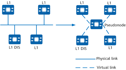
Network with a pseudonode
Process of synchronizing LSDBs between a newly added routing device and the DIS on a broadcast link
- As shown in the following figure, DeviceC, which is newly added to the network, first sends Hello packets to establish neighbor relationships with DeviceA and DeviceB in the broadcast domain. After the neighbor relationships are established, DeviceC waits until the LSP update timer expires and sends its LSP to its neighbors. In this manner, all neighbors on the network receive this LSP.
- The DIS on the network segment adds the LSP received from DeviceC to its LSDB. After the CSNP timer expires, the DIS sends CSNPs to synchronize LSDBs on the network.
- After receiving the CSNP from the DIS, DeviceC checks its LSDB and sends a PSNP to the DIS to request the LSPs that it does not have.
- After receiving the PSNP, the DIS sends the corresponding LSPs to DeviceC for LSDB synchronization.
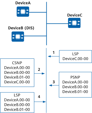
Process of synchronizing LSDBs on a broadcast link
- When the DIS receives an LSP, it searches its LSDB for related records. If the DIS finds no match, it adds the LSP to its LSDB and broadcasts the content of the updated LSDB.
- If the sequence number of the received LSP is greater than that of the corresponding LSP in the LSDB, the DIS replaces the existing LSP with the received LSP and broadcasts the contents of the updated LSDB. If the sequence number of the received LSP is smaller than that of the corresponding LSP in the LSDB, the DIS sends its LSP in the LSDB through the inbound interface of the received LSP.
- If the sequence number of the received LSP is the same as that of the corresponding LSP in the LSDB, the DIS compares the Remaining Lifetime of the two LSPs. If the Remaining Lifetime of the received LSP is smaller than that of the corresponding LSP in its LSDB, the DIS replaces the local LSP with the received LSP and broadcasts the updated LSDB. If the Remaining Lifetime of the received LSP is greater than that of the corresponding LSP in its LSDB, the DIS sends the local LSP through the inbound interface of the received LSP.
- If the sequence number and Remaining Lifetime of the received LSP are the same as those of the corresponding LSP in the LSDB, the DIS compares the Checksum of the two LSPs. If the Checksum of the received LSP is greater than that of the corresponding LSP in its LSDB, the DIS replaces the local LSP with the received LSP and broadcasts the updated LSDB. If the Checksum of the received LSP is smaller than that of the corresponding LSP in its LSDB, the DIS sends the local LSP through the inbound interface of the received LSP.
- If the received LSP and the corresponding LSP in the LSDB share the same sequence number, Remaining Lifetime, and Checksum, the DIS does not forward the received LSP.
DIS Election
On a broadcast network, any two routers exchange information. If n routers are available on the network, n x (n – 1)/2 adjacencies must be established. Each state change of a router is transmitted to other routers, which wastes bandwidth. IS-IS resolves this problem by defining the DIS. All routers send information to the DIS, which then broadcasts the network link states. Using the DIS and pseudonodes simplifies network topology and reduces the length of LSPs generated by routers. In addition, when the network changes, fewer LSPs are generated, reducing SPF resource consumption.
A DIS is elected after a neighbor relationship is established. Level-1 and Level-2 DISs are elected separately. You can configure different priorities for DISs at different levels. In IS-IS DIS election, a Level-1 priority and a Level-2 priority are specified for each router interface. A router sends Hello packets through each interface and advertises its priority in the Hello packets. The device with the largest DIS priority value is elected as the DIS. If there are multiple routers with the same highest priority, the one with the highest MAC address is elected. The DISs of different levels can be the same router or different routers.
- The router with the priority of 0 also takes part in the DIS election.
- When a new router that meets the requirements of being a DIS is added to the network, the router is elected as the new DIS. This change causes a new round of LSP flooding.
LSDB Synchronization on a P2P Link
After establishing a P2P neighbor relationship, two devices send CSNPs to each other. If the LSDB of the neighbor and the received CSNP are not synchronized, the neighbor sends a PSNP to request the required LSP.
As shown in the following figure, DeviceB requests an LSP from DeviceA. DeviceA starts the LSP retransmission timer while sending the LSP requested by DeviceB, and then waits for a PSNP from DeviceB as an acknowledgment of the LSP.
If DeviceA does not receive a PSNP from DeviceB after the LSP retransmission timer on the interface expires, DeviceA retransmits the LSP until it receives a PSNP.

On a P2P link, a PSNP can be used as an ACK to acknowledge received LSPs and to request required LSPs.
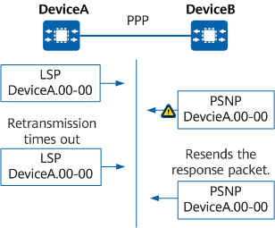
Process of updating LSDBs on a P2P link
How Is Route Calculation Performed?
IS-IS uses the shortest path first (SPF) algorithm to calculate routes, implementing fast route convergence.
IS-IS uses LSAs to describe the network topology (directed graph). A router LSA describes the attributes of a link between devices. A device transforms its LSDB into a weighted, directed graph, which reflects the topology of the entire network. All devices obtain the same directed graph, as shown in the following figure.
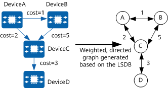
Weighted, directed graph generated based on the LSDB
Based on the directed graph, each device uses the SPF algorithm to calculate an SPT with itself as the root. The SPT shows routes to nodes in the AS. The following figure shows SPTs.
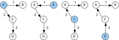
SPTs
If a device's IS-IS LSDB changes, the device recalculates the shortest path. However, frequent SPF calculations consume a large number of resources and this can affect the overall efficiency of the device. Setting a proper interval between SPF calculations can address this problem. The default interval between SPF calculations is 5 seconds.
The calculation process is as follows:
A device calculates intra-area routes.
The device uses the SPF algorithm to calculate shortest paths to the other devices in the same area. Router-LSAs and Network-LSAs accurately describe the network topology in an area. Based on the network segment information described by router LSAs, the device obtains the specific path to each network segment.
If there are multiple equal-cost routes during route calculation, the SPF algorithm retains all the equal-cost routes in the LSDB.
The device calculates inter-area routes.
For devices in the same area, the network segment of the routes in an adjacent area is directly connected to the ABR. As the shortest path to the ABR has already been calculated in the previous step, the devices can directly check a Network-Summary-LSA to obtain the shortest path to the network segment. The ASBR can also be considered connected to the ABR. Therefore, the shortest path to the ASBR can also be calculated in this phase.
- If the device performing an SPF calculation is an ABR, the device only needs to check network summary LSAs in the backbone area.
The device calculates AS external routes.
AS external routes can be considered to be directly connected to the ASBR. Because the shortest path to the ASBR has been calculated in the preceding phase, the device can check AS External LSAs to obtain the shortest paths to other ASs.
IS-IS Extensions
IS-IS for IPv6
The IETF standard protocol defines the contents added to IS-IS to support IPv6. Specifically, two Type-Length-Values (TLVs) and a Network Layer Protocol Identifier (NLPID) are added so that IS-IS can process and calculate IPv6 routes.
The two TLVs are as follows:
IPv6 Reachability
The type is 236 (0xEC). It describes network reachability by defining information such as route prefixes and metrics.
IPv6 Interface Address
The type value is 232 (0xE8). It is equivalent to the IP Interface Address TLV in IPv4, except that the original 32-bit IPv4 address is changed to a 128-bit IPv6 address.
The NLPID is an 8-bit field that identifies network layer protocol packets. The NLPID of IPv6 is 142 (0x8E). If IS-IS supports IPv6, IPv6 routes advertised by IS-IS must carry NLPID values.
IS-IS for SR-MPLS
Segment Routing (SR) is designed to forward data packets using the source routing mechanism. Segment Routing MPLS (SR-MPLS) is implemented based on the MPLS forwarding plane and is referred to as SR hereinafter. SR divides a network path into segments and allocates a segment ID (SID) to each segment and forwarding node. The segments and nodes are then sequentially arranged into a segment list to form a forwarding path.
SR encapsulates segment list information that identifies a forwarding path into the packet header for transmission. After receiving a packet, the receive end parses the segment list. If the SID at the top of the segment list identifies the local node, the node removes the SID and executes the follow-up procedure. If the SID at the top does not identify the local node, the node forwards the packet to the next hop in equal cost multiple path (ECMP) mode.
SR-MPLS uses an IGP to advertise topology, prefix, Segment Routing global block (SRGB), and label information. This is achieved by extending the TLVs of protocol packets for IS-IS. IS-IS extends SIDs and SR-MPLS sub-TLVs.
The following figure shows the format of an IS-IS LSP carrying SR information.
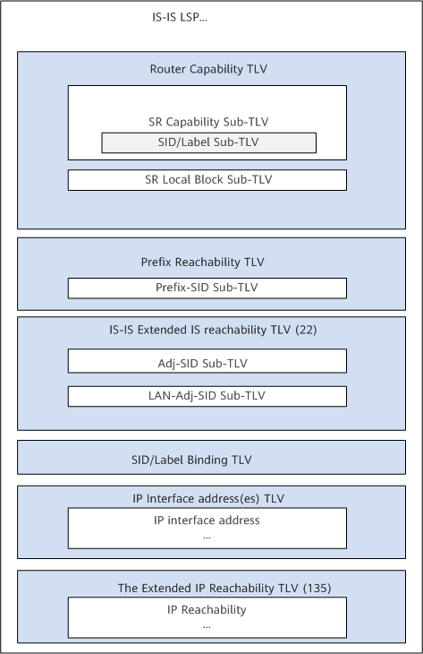
Format of an IS-IS LSP carrying SR information
- Prefix-SID Sub-TLV: advertises SR-MPLS prefix SIDs.
- Adj-SID Sub-TLV: advertises SR-MPLS adjacency SIDs on a P2P network.
- LAN-Adj-SID Sub-TLV: advertises SR-MPLS adjacency SIDs on a LAN.
- SID/Label Sub-TLV: advertises SR-MPLS SIDs or MPLS labels.
- SID/Label Binding TLV: advertises the mapping between prefixes and SIDs.
- SR-Capabilities Sub-TLV: advertises local SR-MPLS capabilities.
- SR Local Block Sub-TLV: advertises the range of labels reserved by an NE for local SIDs.
IS-IS for SRv6
Segment Routing IPv6 (SRv6) forwards IPv6 packets using the source routing model. Specifically, SRv6 implements hop-by-hop forwarding by adding a Segment Routing header (SRH) into IPv6 packets, encapsulating an explicit IPv6 address stack into the SRH, and continuously updating IPv6 destination addresses while offsetting the address stack at each transit node.
SR uses an IGP to advertise topology, prefix, locator, and SID information. This is achieved by extending the TLVs of protocol packets for IS-IS.
The following figure shows the format of an IS-IS LSP carrying SRv6 information.
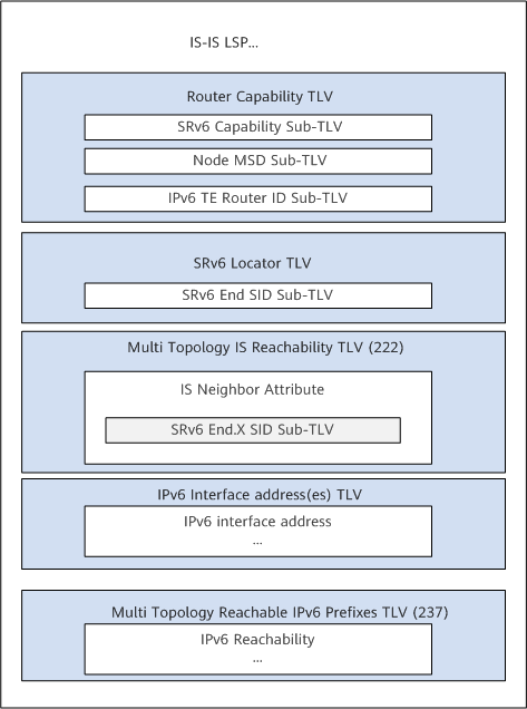
Format of an IS-IS LSP carrying SRv6 information
- SRv6 Locator TLV: advertise an SRv6 locator and the End SIDs associated with it.
- SRv6 Capabilities sub-TLV: advertises SRv6 capabilities.
- SRv6 End SID sub-TLV: advertises SRv6 SIDs.
- SRv6 End.X SID sub-TLV: advertises SRv6 SIDs on a P2P network.
- SRv6 LAN End.X SID sub-TLV: advertises SRv6 SIDs on a LAN.
- Node MSD sub-TLV: advertises the maximum SID depth (MSD) that a device can accept.
What Are the Differences Between IS-IS and OSPF?
The differences between IS-IS and OSPF are as follows:
- Protocol type: OSPF uses the IP-layer protocol, whereas IS-IS uses the link layer protocol.
- Protocol extensibility: OSPF extends LSA types to meet new requirements, which is average in extensibility. For example, OSPFv3 is required to support IPv6. IS-IS has high extensibility due to its TLV packet structure. For example, only the TLV needs to be extended to support IPv6.
- Application scope: OSPF applies to medium-scale networks with a maximum of hundreds of devices, small- and medium-sized enterprise networks for example. IS-IS applies to large-scale networks, large ISP networks for example.
- Routing algorithm: OSPF uses the SPF algorithm to calculate an SPT to all destinations based on the network topology information, which is advertised through LSAs. IS-IS uses the SPF algorithm to generate an SPT based on the network topology and calculates shortest paths to all destinations on the network. In IS-IS, the SPF algorithm runs independently in Level-1 and Level-2 databases.
- Convergence speed: Both OSPF and IS-IS can complete convergence within 1s.
- Area division: OSPF divides areas by interface, whereas IS-IS divides areas by router.
- Author: Han Ming
- Updated on: 2023-07-20
- Views: 5367
- Average rating:


