What Is MTN?
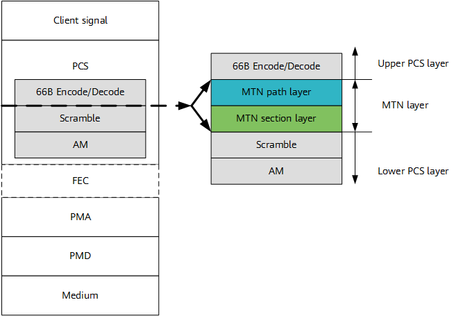
The Metro Transport Network (MTN) is a lightweight architecture for implementing hard isolation. It embeds two new sublayers — path layer and section layer — into the Physical Coding Sublayer (PCS) of the Ethernet. In addition to being compatible with the mainstream Ethernet protocol stack, MTN meets service requirements for hard isolation, low delay, and high reliability in the 5G era, and further improves the transport capabilities of 5G networks.
Why Do We Need MTN?
With the advent of the 5G era, a growing number of industries seek to upgrade their networks vertically. In contrast to traditional 4G networks that use the "one pipe and best effort" mode, 5G networks need to provide E2E network slices (namely, logical private networks) for different services to implement secure and efficient service data transmission on the unified infrastructure and network architecture. In this context, next-generation network technologies must support flexible network slicing, ensure E2E hard isolation, and guarantee deterministic low delay. Slicing Packet Network (SPN) fully meets these requirements. The SPN architecture mainly consists of the following layers:
- Slicing Packet Layer (SPL): implements addressing-based forwarding and transport channel encapsulation for IP, Ethernet, and Constant Bit Rate (CBR) services, and provides multiple service types such as L2VPN, L3VPN, and CBR transparent transmission.
- Slicing Channel Layer (SCL): uses the TDM timeslot-based MTN path and section layer technologies to provide E2E channels for network services and slices.
- Slicing Transport Layer (STL): provides IEEE 802.3 Ethernet Physical Layer (PHY) encoding/decoding and optical transmission media processing for efficient high-bandwidth transmission.
In the SPN architecture, MTN mainly provides the MTN path and section layers that are essential to the SCL. MTN offers the Ethernet slicing capability based on the native Ethernet kernel. It is fully compatible with Ethernet and prevents caching and table lookup for packets at L2/L3, thereby providing deterministic low delay and hard pipe isolation in L1 channel networking.
Considering this, what is the relationship between MTN and traditional network technologies? As shown in the following figure, MTN is located at Layer 1.5, that is, between the PHY and the data link layer. Specifically, MTN embeds an MTN path layer and an MTN section layer into the PCS, dividing the PCS into upper and lower layers.
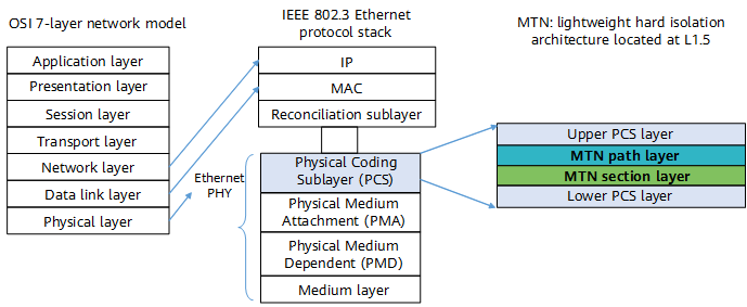
MTN position in the OSI model
One thing to note is that both the MTN path layer and section layer are designed based on 66B blocks. This offers the following advantages:
Hard Slice Isolation
TDM timesloting and switching are performed on a per-66B block basis over the Ethernet, implementing hard slice isolation.
As shown in the following figure, blocks ABCDEFG indicate 66B blocks that are encoded from Ethernet frames. Block A belongs to the Ethernet frame A. Several blocks A can form the complete Ethernet frame A after being decoded. The same is true for the other blocks. Encoding and decoding fall under the Ethernet Layer 2 protocol, and therefore are omitted here.
Different MTN path layers upload the blocks that belong to different frames into the corresponding timeslots in a fixed sequence. For example, if the rate of MTN path 1 is 10 Gbit/s, path 1 needs to occupy two timeslots (timeslots 3 and 6) of the MTN section-layer frame to carry signals. At the source end, 66B blocks of path 1 are sequentially mapped to timeslots 3 and 6 of the MTN section-layer frame. After receiving the data, the sink end performs demapping, and restores the 66B block sequence of path 1 from timeslots 3 and 6.
Given this, hard slice isolation means that 66B blocks of different Ethernet frames are isolated and transmitted along the MTN section-layer links without affecting each other as they occupy fixed timeslots.
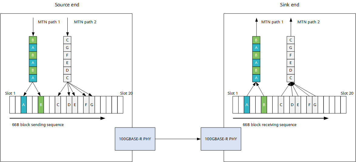
Mapping and demapping of the MTN path layer
Low Forwarding Delay
Networking is completed at L1 (PHY), eliminating the need for caching and table lookup at L2/L3 (data link/network layer) during packet forwarding and in turn reduces the forwarding delay.
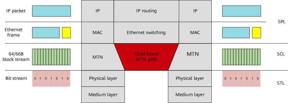
Comparison of the switching technology at L1.5 and at L2/L3
High Compatibility
Signals at the lower PCS layer are also 66B blocks. This means that MTN is widely compatible with the traditional Ethernet protocol stack, increasing the return on investment of operators.
As shown in the right part of the following figure, after the MTN path layer and section layer are introduced, the PCS is divided into the upper and lower PCS layers.
- Both the MTN path layer and section layer are designed based on 66B block streams, and the signals they transmit to the lower PCS layer share the same format as the signals carried at the PCS layer in the Ethernet protocol stack; that is, both are 66B blocks. Next, the Physical Medium Attachment (PMA), a processing module also oriented at 66B block streams, does not distinguish or identify blocks, meaning that the PMA is compatible with MTN. In addition, the Physical Medium Dependent (PMD) and Medium are both bit stream-oriented processing modules, and as such are also compatible with MTN.
- After 66B encoding at the upper PCS layer, client signals (for example, an IP packet or a MAC frame) are converted into 66B block streams, and any packet information is transparent to the MTN layer. For this reason, MTN is compatible with L2/L3 packet forwarding technologies.
Compatibility between the MTN layer and the Ethernet upper and lower layersOwing to the preceding characteristics, MTN meets the key requirements of the 5G era, such as high bandwidth, low delay, and slicing, and provides a converged and unified transport platform for various services. As such, MTN — an essential part of the layered SPN network — is favored by network operators when constructing next-generation transport networks.
How Is MTN Implemented?
To understand how MTN is implemented, we need to first understand its technical architecture and networking mode.
Technical Architecture of MTN
MTN architecture consists of three layers, listed here from bottom to top: MTN optical media layer, MTN layer, and MTN client signal. The MTN layer is further divided into MTN section layer and MTN path layer. The following figure shows its technical architecture.
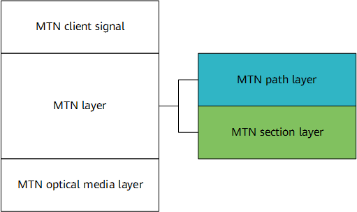
Technical architecture of MTN
The following details the functions of each layer.
- The MTN optical media layer shares the same working principle as the Ethernet optical media layer. They both use the signal transceiver to provide point-to-point fixed-rate connections. Currently, the MTN optical media layer defined in IEEE 802.3 contains four types of Ethernet PHYs: 50GBASE-R, 100GBASE-R, 200GBASE-R, and 400GBASE-R. According to the numbering convention for the PHYs in IEEE 802.3, the left-most numbers indicate their supported rates, which are 50 Gbit/s, 100 Gbit/s, 200 Gbit/s, and 400 Gbit/s, respectively.
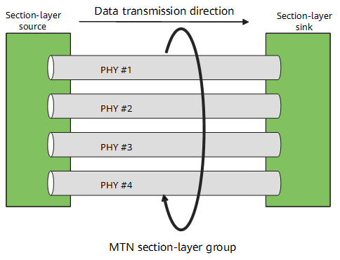
- The MTN section layer provides point-to-point connectivity for the MTN path layer through the MTN optical media layer. The following figure shows its basic architecture.
Basic architecture of the MTN section layerThe MTN section layer performs timeslot processing on the 66B block streams at the Ethernet optical media layer and introduces the TDM frame structure to support the following functions.Table 1-1 Functions supported by the MTN section layerFunction
Purpose
Example
Binds multiple PHYs into one group.
Provides higher physical-layer bandwidth.
Binds three 100GBASE-R PHYs to one MTN section-layer group to carry a 300 Gbit/s MTN path.
Divides a single PHY into several lower-rate PHYs.
Provides sub-rates.
Divides a 100GBASE-R PHY into five 20 Gbit/s MTN paths.
Splits channels on a single PHY or a bundled section-layer group.
Provides the channelization function.
Uses a section-layer group that has three 100GBASE-R PHYs bundled to carry two MTN paths: one is 50 Gbit/s, and the other is 250 Gbit/s.
- The MTN path layer forwards 66B block streams through a path that is formed by connecting the MTN section layers of multiple devices hop by hop, thereby providing an E2E hard slicing service for MTN client signals.
The following figure shows the relationship between the MTN path and section layers. The figure assumes that an MTN path passes through five Network Elements (NEs) — NE1, NE2, NE3, NE4, and NE5 — and occupies the same bandwidth (same number of timeslots) on each MTN section-layer link. In addition, the MTN path layer inserts an Operation, Administration, and Maintenance (OAM) message at the source end, and extracts it at the sink end to monitor its Service Level Agreement (SLA) indicators.
Relationship between the MTN path layer and section layer - An MTN client signal is an Ethernet frame, which can be an MPLS, Segment Routing (SR), IPv4, or IPv6 packet that is encapsulated using Ethernet. After being encoded using 64B/66B, the Ethernet frame becomes a 66B block sequence, which is then mapped to the MTN path.
Typical MTN Networking
The following figure shows what a typical metro transport network is like.

Typical metro transport network
Typically, a transport network provides a connection channel for client signals. This channel can be a logical virtual connection or a physical fiber connection. In the SPN solution, the metro transport network mainly uses MTN to build E2E rigid hard pipe connections. The typical MTN networking can be abstracted as follows.
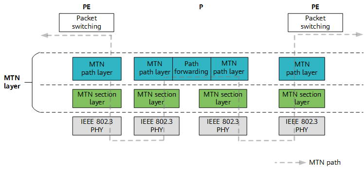
Typical MTN networking
MTN establishes a transmission path between the source and sink nodes to provide an E2E Ethernet slice connection. This path is constructed using the following three steps:
- The source node maps the client-layer service into an MTN path.
- The network intermediate nodes forward the service as an Ethernet 66B block sequence.
- The sink node demaps the client-layer service from the MTN path.
This implements various functions such as access and restoration of client data, addition and deletion of OAM information, cross-connect of data streams, and path monitoring and protection. As well as this, it provides low delay, transparent transmission, and hard isolation.
Where Can MTN Be Used?
MTN can be used in the typical solutions for verticals' 5G transport networks to meet distinct transport requirements. Specifically, it allows you to select a tailored slice type based on your requirements and to determine other information (such as the bandwidth granularity, protection scheme, and service quality detection method) after taking into account the isolation features of different slices and the coverage scope of your transport network. The following table lists four MTN-based slice types and their respective service application scenarios.
Slice Type |
Priority |
Isolation Mode |
Example Application Scenario |
|---|---|---|---|
Luxury slice |
Highest |
Hard isolation |
Private network slice for industry VIP customers to meet their highest isolation and low delay requirements |
Exclusive slice |
High |
Hard isolation/Soft isolation |
Private network slice for industry VIP customers |
ToB shared slice |
Medium |
Soft isolation |
Private network slices for industry common customers |
ToC shared slice |
Low |
Soft isolation |
eMBB service slice over the public network |
Based on the preceding content, the following describes how MTN empowers specific 5G service scenarios.
MTN Application in 5G ToB Smart Grid
Depending on where the Multi-access Edge Computing (MEC) and User Plane Function (UPF) are deployed, the typical networking scenarios of the next-generation smart grid are classified into three types: regional centralized networking, multi-point distributed networking, and local substation networking.
- Regional centralized networking: The MEC/UPF is deployed at the core or aggregation node. All power services in zones I, II, III, and IV are terminated at the power dispatch center where the core or aggregation node is located. The service termination points of multiple power slices are the same; that is, they are generally located in the regional center of a city.
- Multi-point distributed networking: It applies to city-based large-area networking scenarios. MECs and UPFs are deployed in the dispatch centers and substations where core and aggregation nodes are located. Power services in zones I and II are processed in the dispatch center, and those in zones III and IV are terminated at a substation. The service termination points of multiple power slices are different.
- Local substation networking: The MEC/UPF is deployed at a substation where an access, core, or aggregation node of the transport network may be located. It is mainly used to locally process power surveillance video services of the substation. Note that deployment location and coverage of power slices vary with networking modes.
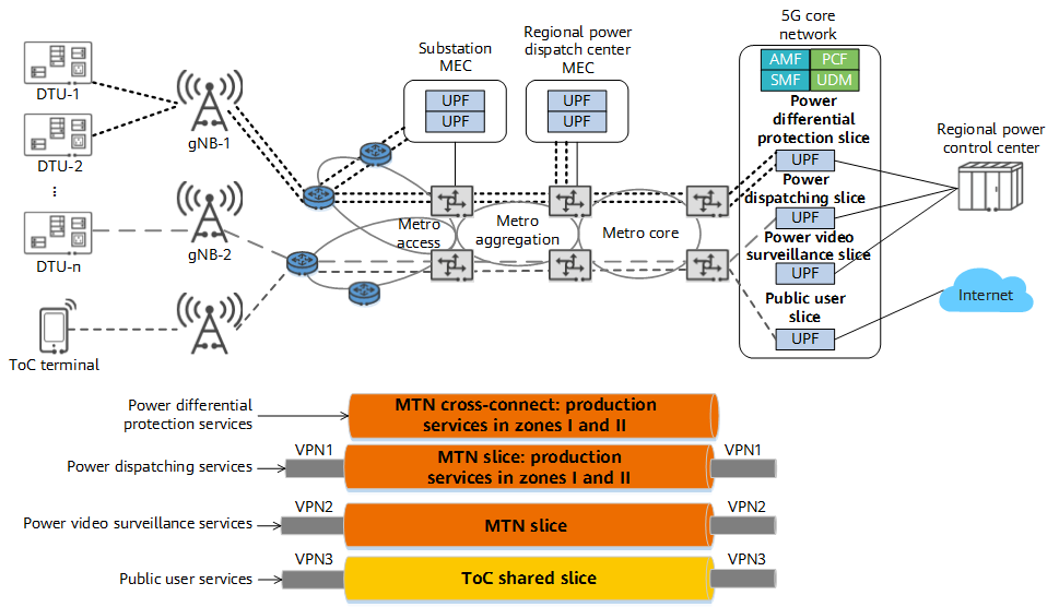
5G ToB smart grid transport solution
In zones I and II, production services — such as differential protection and power dispatching automation services — are sensitive to delay. In this case, MTN slices can be used to implement hard service isolation, ensuring service security and meeting their performance requirements, such as deterministic low delay and low jitter. In zones III and IV, power video surveillance services are management services. They can be isolated from other services using other types of MTN slices. Within the slices, VPNs and QoS priorities can be used for service scheduling to ensure the performance of high-priority services. The following table describes the MTN-based solution for power grid services.
Service Type |
Slice Type |
Isolation Capability |
Typical Application |
|---|---|---|---|
Production control (zones I and II) |
Exclusive slice |
MTN path/MTN interface |
Differential protection services |
Exclusive slice |
MTN path/MTN interface |
Power dispatching automation services |
|
Information management (zones III and IV) |
Exclusive slice |
MTN path/MTN interface and VPN |
Power video surveillance services |
MTN Application in 5G ToB Smart Healthcare
5G ToB smart healthcare services are classified as intra-, inter-, or pre-hospital services. For intra- and inter-hospital services, the main challenge facing the transport network is providing low delay and security isolation. To ensure stable low delay (less than 5 ms) and industry private networks for dedicated use, the transport network needs to provide network slices with hard isolation. For pre-hospital first-aid services, the main challenge facing the transport network is creating dedicated channels quickly and flexibly to ensure high-quality transmission anytime and anywhere. The following figure shows the MTN-based smart healthcare transport solution for the three types of healthcare services.
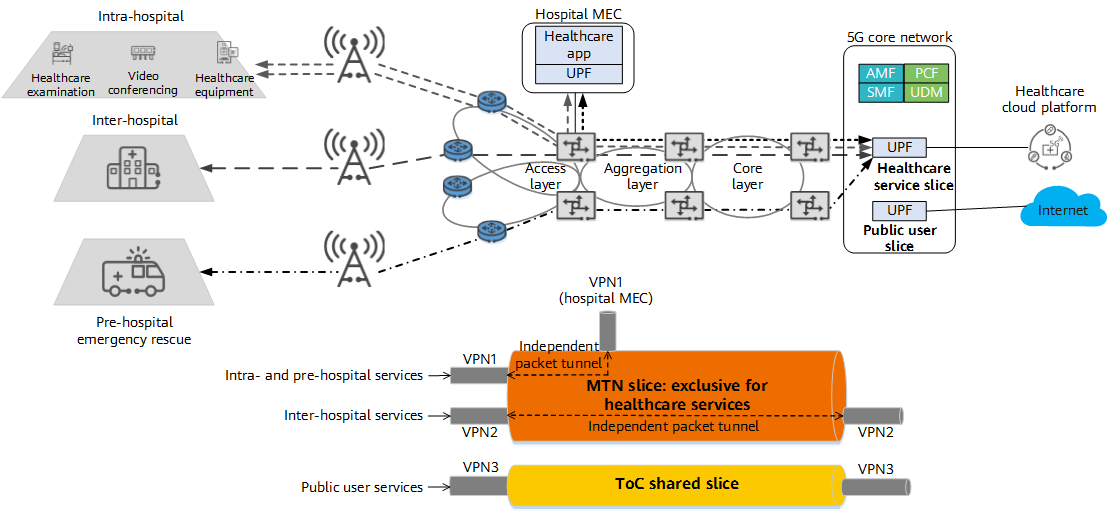
MTN-based 5G ToB smart healthcare transport solution
5G ToB smart healthcare uses MTN to achieve E2E network slices, ensuring service security isolation and service quality of the healthcare private network. As described in the following table, healthcare services can be carried over two independent packet tunnels in an exclusive slice based on service mobility characteristics.
- Intra-, pre- and inter-hospital services have local mobility and can be isolated by different VPNs in exclusive slices (that is, MTN paths).
- Pre- and intra-hospital services share the similar application scope, and therefore can share an independent packet tunnel. Inter-hospital services span a larger region and need to be carried by another independent packet tunnel.
Service Type |
Slice Type |
Isolation Capability |
Typical Application |
|---|---|---|---|
Intra-/Pre-hospital services |
Exclusive slice |
MTN interface and VPN |
Mobile ward rounds, wireless monitoring, and ambulance |
Inter-hospital services |
Exclusive slice |
MTN interface and VPN |
Wireless remote consultation and remote surgery demonstration |
The transport network for intra-, pre- and inter-hospital services provides exclusive healthcare slices to carry these services. This meets requirements for data security isolation and low-delay, high-quality transmission between healthcare devices such as 5G terminals and other communication access devices within and between hospitals.
MTN Application in 5G ToB Smart Ports
Modern ports have lots of heavy machinery and various networking requirements, covering aspects such as control, monitoring, and converged communication. Traditional port solutions typically employ optical fiber and Wi-Fi interconnection, but these networking communication modes have problems such as high construction and O&M costs and poor stability and reliability. 5G ToB smart ports combine industrial control with 5G networks — featuring low delay, high bandwidth, and high reliability — to implement port intelligence through technologies such as video backhaul and remote control.
A smart port has the following typical requirements on the 5G transport network:
- Programmable Logic Controller (PLC) control services, represented by crane control, require the network to have low-delay and high-reliability transport capabilities. Specifically, one crane requires an E2E delay of less than 18 ms, a bandwidth of 50 kbit/s to 100 kbit/s, and 99.999% reliability.
- Video surveillance services, represented by High Definition (HD) cameras, require the network to have high-bandwidth and low-delay transport capabilities. Specifically, an HD video surveillance device must be able to provide a bandwidth of 30 Mbit/s to 200 Mbit/s.
To meet a port's differentiated service requirements, the 5G transport network uses MTN-based network slices to carry different types of services.
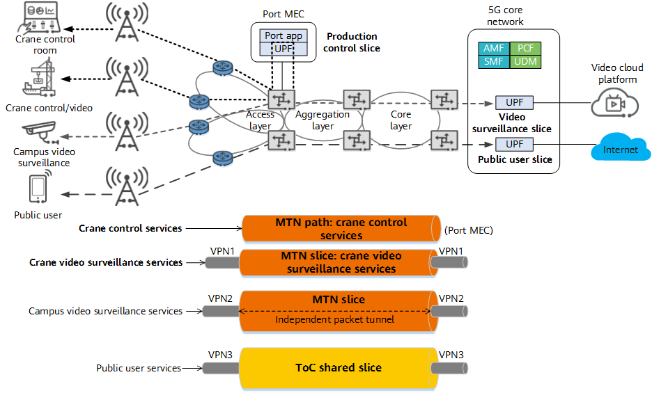
MTN-based 5G ToB smart port transport solution
MTN is used to create network slices over the 5G transport network of a smart port, thereby providing differentiated transport services. The specific deployment can be as follows:
- For remote operation and control services, 5G needs to provide fixed-point coverage for the port to ensure high security, reliability, and extremely low delay. In this case, private network-specific slices can be used for independent transport.
- For video surveillance services, 5G needs to cover the entire port area. While these services require lower reliability than operation and control services, they require high bandwidth and low delay. Public network-specific slices can be used to carry these services.
Service Type |
Slice Type |
Isolation Capability |
Typical Application |
|---|---|---|---|
Remote operation and control services |
Private network-specific slice |
MTN path |
Remote crane control and unmanned container truck |
Video surveillance services |
Exclusive slice |
MTN interface and VPN |
Security monitoring of the port area |
Crane operation and control is the most important production service of a port. Related labor costs can be reduced by using 5G to remotely control cranes. In order to mitigate the risks introduced by remote control, the network delay must be lowered. To this end, crane control must be isolated from other services through timeslots to ensure transmission performance such as low delay and low jitter between the crane and the remote control console.
Video surveillance is a common management service application in the port. It can be isolated from other services through VPNs. Based on the preset service priorities, QoS scheduling can be implemented for these VPN services to ensure the transmission performance of high-priority services.
With the wide application of MTN in various industries, its technical advantages of high quality, high security, and high flexibility are fully proven to support the digital transformation of industries. Beyond that, MTN will continue to improve in order to meet requirements of diverse services, such as refined slicing, flexibility, and intelligence, gradually entering the MTN 2.0 era.
- Author: Cai Yi
- Updated on: 2022-08-05
- Views: 3451
- Average rating:


