NPCC
Network-based Proactive Congestion Control (NPCC) is a proactive congestion control technology centering on network devices. It intelligently identifies the congestion status on network devices, enables devices to proactively send Congestion Notification Packets (CNPs), and accurately controls the rate of Remote Direct Memory Access (RDMA) over Converged Ethernet version 2 (RoCEv2) packets sent by the server. This ensures timely rate reduction upon congestion and prevents excessive rate reduction when congestion is relieved.
Why Do We Need NPCC?
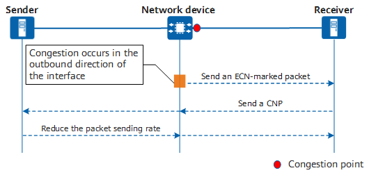
Currently, the most widely applied congestion control mechanism on a Remote Direct Memory Access (RDMA) over Converged Ethernet version 2 (RoCEv2) network is described as follows: After a network device detects congestion, it sends an Explicit Congestion Notification (ECN)-marked packet to the server at the receive end (receiver), which then sends a Congestion Notification Packet (CNP) to the server at the transmit end (sender), notifying the sender to reduce its packet transmission rate.

Traditional congestion control mechanism
- Slow response: Congestion occurs on a network device but the CNP is sent by the final receiver. This means that if the network scale is large, a long congestion feedback path may lead to the sender being unable to reduce the packet sending rate in a timely manner or even to increase the rate in advance, further exacerbating congestion.
- Inaccurate response: The network congestion status can be obtained only through the ECN field in a packet, and a certain number of CNPs generated by the receiver cannot accurately relieve the congestion. In addition, in a congestion relief process, the network device (known as the forwarding device) continues to perform ECN marking, which easily leads to a low throughput.
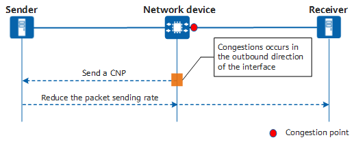
Network-based Proactive Congestion Control (NPCC) enables network devices to intelligently identify the congestion status and proactively send CNPs to the sender so that the sender can reduce the packet sending rate in a timely manner. In this way, the problem of a long congestion feedback path is solved, and the number of CNPs to be sent can be controlled accurately. This ensures timely rate reduction upon congestion and prevents excessive rate reduction when congestion is relieved. However, when NPCC is enabled, network devices need to maintain the RoCEv2 flow table, calculate the number of CNPs, and construct and send CNPs. This process takes a relatively long time. Considering this, NPCC is more beneficial when the servers at the two ends are far away from each other.

Congestion control mechanism of NPCC
How Does NPCC Work?

NPCC Fundamentals
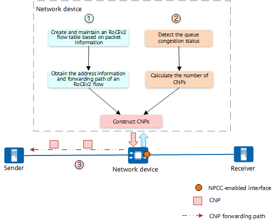
The preceding figure shows how NPCC works.
- Maintaining an RoCEv2 flow table and obtaining path information
An NPCC-enabled network device creates and maintains an RoCEv2 flow table based on the source IP address, destination IP address, Dest QP field, and interface index of the packet to obtain the address information and forwarding path of each RoCEv2 flow.
- Detecting the congestion status of a queue and calculating the number of CNPs
The network device detects the length (buffer usage) of an NPCC-enabled queue on the NPCC-enabled interface and intelligently calculates the number of CNPs to be sent based on the queue's congestion status.
- If the queue length increases: When the queue is shallow, the network device sends a small number of CNPs to prevent incorrect determination of the congestion status. When the queue is deep, the network device sends a large number of CNPs to quickly relieve queue congestion and reduce the forwarding latency.
- If the queue length decreases: When the queue is shallow, the network device does not send CNPs, preventing the throughput from decreasing due to excessive rate reduction. When the queue is deep, the network device sends a small number of CNPs to relieve queue congestion while maintaining the highest-possible throughput and lowest-possible latency.
- If the queue has a sudden low jitter: The network device considers that a microburst has occurred and therefore does not send CNPs, preventing excessive rate reduction.
- Constructing and forwarding CNPs
The network device constructs CNPs based on the number of CNPs calculated and the address information in the RoCEv2 flow table. It then proactively sends the CNPs to the sender. After receiving the CNPs, the sender reduces the rate at which it sends RoCEv2 packets.
NPCC Application
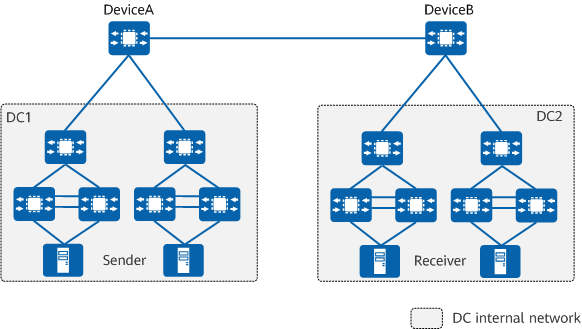
As shown in the following figure, in a long-distance Data Center Interconnect (DCI) scenario, DeviceA and DeviceB function as egress devices for DCI. When congestion occurs on the outbound interface of DeviceA, DeviceA sends an ECN-marked packet to the server at the receive end (receiver) in DC2, which then sends a CNP to the server at the transmit end (sender) in DC1. When receiving the CNP, the sender reduces its packet sending rate. This process takes a long time since the two data centers are far away. As a result, the packet sending rate cannot be reduced in a timely manner.
After NPCC is enabled on DeviceA, when congestion occurs on the outbound interface of DeviceA, DeviceA directly sends a CNP to the sender in DC1. This reduces the packet sending rate and relieves congestion in a timely manner.

Long-distance DCI scenario
- Author: Feng Yuanyuan
- Updated on: 2024-02-27
- Views: 5406
- Average rating:


