What Is Financial WAN Data Redundancy Elimination?
Driven by booming smart finance, the traffic between financial DCs and branches is increasing sharply, leading to spiraling WAN private line bandwidth leasing costs: two to three times that of the investment made in actual network devices. The financial WAN data redundancy elimination solution compresses data at the transmit end and decompresses the data at the receive end. This reduces the line bandwidth resources consumed by WAN traffic transmitted between financial DCs and branches, saves line costs, and accelerates the deployment of distributed DCs.
Why Do We Need WAN Data Redundancy Elimination?
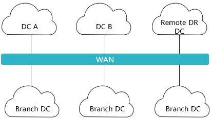
The finance industry is adapting to the trend of multiple distributed DCs, leading to surging traffic between DCs. As shown in Figure 1-2, WAN links are leased to transmit traffic between DCs. The line rental cost is proportional to the bandwidth. Statistics show that the WAN line rental cost of financial institutions is two to three times that of the investment made in actual network devices.
This is where the financial WAN data redundancy elimination solution comes in. In this solution, the transmit end compresses the data before the data is forwarded over WAN links, and the receive end decompresses the received data to restore the original data. This minimizes the consumed WAN bandwidth resources, significantly slashes WAN line rental costs, and ultimately accelerates the deployment of distributed DCs.
Overall Architecture
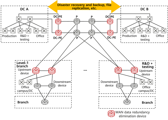
Figure 1-3 shows the overall architecture of the financial WAN data redundancy elimination solution. DC-PEs and upstream devices of level-1 branches (marked in red) are responsible for data compression and decompression. The source and destination IP addresses and port numbers of data packets remain unchanged before and after compression. Compressed packets can be sent over Segment Routing over IPv6 (SRv6) tunnels, implementing on-demand route selection.
To use the WAN data redundancy elimination function, you simply need to install data redundancy elimination boards on NE routers that compress and decompress data, and activate the data redundancy elimination license on the NE routers and NCE controller. In this way, traffic can be diverted, compressed and decompressed, and forwarded without needing to deploy additional data redundancy elimination devices or changing the network topology.
Data Compression Protocol
IP Payload Compression Protocol (IPPCP), also known as IPComp, is a lower-layer compression protocol oriented to IP data packets. Different from the payload in a common IP packet, the payload in an IPPCP packet is compressed.
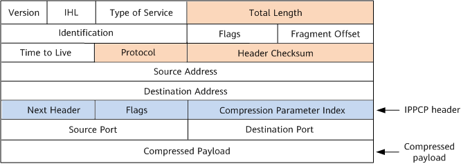
IPPCP compresses IP packets by inserting the IPPCP header and changing some fields in IPv4 and IPv6 packets. Table 1-1 describes the fields.
Field |
Length |
Meaning |
|---|---|---|
Next Header |
8 bits |
It identifies the Protocol field of the original IPv4 packet or the Next Header field of the IPv6 packet. |
Flags |
8 bits |
It is reserved for future use and must be set to 0. |
Compression Parameter Index |
16 bits |
It identifies a compression algorithm. The values 0 to 63 identify well-known compression algorithms (no additional information is required when these algorithms are used). The values 64 to 255 are reserved for future use. |
The following describes the formats of IPv4 and IPv6 packets after they are compressed using IPPCP.
Format of a compressed IPv4 packet
As shown in Figure 1-5, in addition to the IPPCP header being inserted, the values of the three fields marked in orange in the compressed IPv4 packet are changed:
- Total Length: length of the encapsulated IP packet, including the IP header, IPPCP header, and compressed payload.
- Protocol: The value is 108, indicating that the protocol type is IPPCP.
- Header Checksum: used to check whether the IP header changes after being transmitted to the receiver.
Format of a compressed IPv6 packet
As shown in Figure 1-6, in addition to the IPPCP header being inserted, the values of the two fields marked in orange in the compressed IPv6 packet are changed:
- Payload Length: length of the compressed payload.
- Next Header: The value is 108, indicating that the protocol type is IPPCP.
IPPCP — a compression protocol at the IP layer — implements lossless compression. This means that after a packet is compressed and then decompressed, it is the same as that before compression. In addition, because packet loss or disorder may occur, IPPCP implements stateless compression, whereby each packet is independently compressed and decompressed without reliance on other packets. Each packet is encapsulated separately after being compressed.
Data Compression Algorithms
Currently, NE routers support the Zstandard (Zstd) algorithm, which is a high-performance lossless compression algorithm. This algorithm combines a dictionary-based compression algorithm with a statistical model-based compression algorithm to provide a high compression ratio and a high compression speed. The Zstd algorithm also supports multiple compression levels, allowing users to adjust the compression level as required to balance the compression speed and compression ratio.
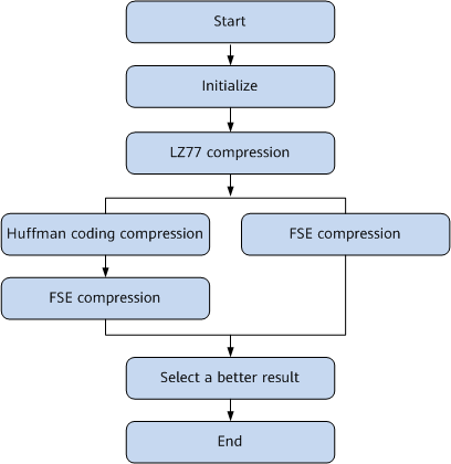
The Zstd algorithm consists of three parts: LZ77, Huffman coding, and Finite State Entropy (FSE). LZ77 is a classic dictionary-based compression algorithm, and Huffman coding and FSE are statistical model-based compression algorithms.
Figure 1-7 shows the compression process of the Zstd algorithm. The compression process starts with the Zstd algorithm initializing the original data into multiple data blocks. Then, LZ77 compression is performed on each data block. Next, "Huffman coding compression + FSE compression" and FSE compression are performed on the compressed data blocks. Finally, the Zstd algorithm selects the better result and constructs compressed data blocks. The decompression process is the reverse of the compression process.
By combining LZ77, Huffman coding, and FSE, the Zstd algorithm not only achieves a high compression ratio and high compression precision, but also achieves a relatively fast compression speed. Compared with other compression algorithms (such as the Deflate, LZ4, and Zlib algorithms), the Zstd algorithm has high compression performance.
Financial WAN Data Redundancy Elimination Process
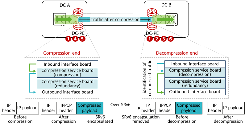
Figure 1-8 shows the financial WAN data redundancy elimination process, which involves configurations on iMaster NCE and network devices (NE routers).
- Preconfigure devices.
- Preconfigure a decompression instance at the decompression end, which is associated with the service board CPU used for compression/decompression and the compression algorithm (Zstd).
- Establish a BGP flow specification peer relationship between the compression end and decompression end.
- Preconfigure a compression instance at the compression end, which is associated with the service board CPU used for compression/decompression and the compression algorithm (Zstd).
- Deliver configurations on iMaster NCE.
iMaster NCE delivers the source IP (SIP), destination IP (DIP), protocol number, source port number, and destination port number of the interesting service flow to the decompression end and delivers the compression algorithm. Either the SIP or DIP must be specified.
- The decompression end finds the decompression instance preconfigured on the device based on the compression algorithm delivered by iMaster NCE. When the service board at the decompression end is functioning properly, the service 5-tuple is converted into a BGP flow specification route, and a BGP flow specification rule is generated locally. This rule contains 5-tuple information and IPPCP compression protocol number 108. The service 5-tuple information and compression algorithm are transmitted to the compression end through the BGP flow specification route.
- After receiving the BGP flow specification route, the compression end generates a dynamic ACL and finds the compression instance based on the compression algorithm carried in the BGP flow specification route.
- The compression end uses the BGP flow specification rule to match, divert, and compress service traffic.
- After receiving a packet, the service board at the compression end matches the packet with the compression policy and forwards the packet to the compression service board.
- The compression service board performs compression, searches the FIB table, encapsulates the packet after compression using SRv6, and then sends the packet over an SRv6 tunnel.
- The packet is forwarded to the outbound interface board and then forwarded out.
- The decompression end performs decompression according to the locally generated decompression instance and policy.
- The interface board receives the compressed packet and removes the SRv6 header.
- The packet matches the decompression policy and is forwarded to the decompression service board.
- The decompression service board decompresses the packet, searches the FIB table, and sends the packet to the outbound interface board.
If the service board on the decompression end fails, the decompression end advertises a BGP flow specification message to the compression end to cancel traffic diversion.
Typical Application Scenarios
Compression does not apply to all service packets.
- Packets that can be compressed: long packets (packets with high redundancy), text, and database (structured packets)
- Packets not recommended for compression: images, videos, check images, and compressed office service packets
For financial services, typical service packets that can be compressed are as follows: remote database replication packets, remote disk replication packets, packets of batch file transfer (a majority of the transferred files are text files), and packets of report transfer.
- Typical application scenario 1: traffic between remote DCs
Remote DCs of financial institutions are usually interconnected through multiple 10G private lines, over which traffic of long-distance disaster recovery in remote storage arrays, remote database backup, and remote data file replication is transmitted. WAN data redundancy elimination can be configured on DC-PEs in DCs to effectively reduce bandwidth consumption of private lines between DCs, thereby reducing line rental costs.
- Typical application scenario 2: traffic between a DC and a level-1 branch
DCs of financial institutions and level-1 branches are usually interconnected through multiple 100M to 1G private lines, over which traffic of patch push, virus library push, application download, and email sending and receiving services is transmitted. WAN data redundancy elimination can be configured on DC-PEs in DCs and upstream devices of level-1 branches to effectively reduce bandwidth consumption of private lines between DCs and level-1 branches, thereby reducing line rental costs.
- Author: Zhang Fan
- Updated on: 2023-10-21
- Views: 1470
- Average rating:


