What Is iNOF?
Intelligent Lossless NVMe Over Fabrics (iNOF) technology allows a device to quickly manage hosts, and applies intelligent lossless network technology to storage systems to implement the convergence of computing and storage networks. This document describes why iNOF is required, how the iNOF network works, association between BFD and iNOF, and a typical application of iNOF.
Why Do We Need iNOF?
In the traditional network architecture, three types of networks (Ethernet, dedicated computing network, and dedicated storage network) are independently deployed, incurring huge deployment and maintenance costs. In addition, the traditional TCP/IP-based Ethernet cannot meet the performance requirements of the storage system. Intelligent lossless network technology can well address these issues. Based on the RDMA over Converged Ethernet version 2 (RoCEv2) protocol, intelligent lossless network technology uses an Intelligent Lossless (iLossless) algorithm that integrates Priority-based Flow Control (PFC) and Artificial Intelligence Explicit Congestion Notification (AI ECN) technologies to implement lossless, low-delay, and high-throughput traffic transmission on an Ethernet, meeting the requirements of storage systems and implementing the convergence of computing and storage networks. A storage system that stores large amounts of data usually needs to manage a large number of hosts, and a growing number of new hosts are connected to network devices in the system.
To enable intelligent lossless network technology to better serve the storage system, iNOF technology is introduced. It enables a device to manage hosts connected to or disconnected from the network and quickly identify network faults, ensuring zero packet loss, low delay, and high throughput on the intelligent lossless network.
How Does the iNOF Network Work?
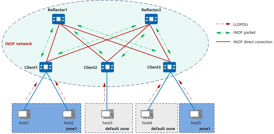
The following figure shows how iNOF is implemented.

Implementation of iNOF
Components of the iNOF network:
- Host: iNOF-capable network server or disk device.
- iNOF reflector: manages connected hosts. An iNOF connection is established between two iNOF reflectors that back up each other. (iNOF reflectors are optional in simple networking.)
- iNOF client: manages connected hosts. An iNOF connection is established between each iNOF client and each iNOF reflector. iNOF clients do not need to establish iNOF connections with each other, and only need to be directly connected to hosts.
- iNOF zone: Hosts are managed based on iNOF zones. The system has a default zone. Users can also customize zones based on service requirements. When a host joins or leaves a zone, iNOF notifies other hosts in the same zone of such information. Hosts in different iNOF zones cannot communicate with each other.
Working process of the iNOF network:
When a new host is connected to the network or an existing host is disconnected from the network, devices on the network perform steps 1 through 4.
Step 1: The host sends an LLDPDU carrying the connection or disconnection information to the connected iNOF client.
Step 2: The client synchronizes the received information to other hosts in the same zone and the connected reflectors through iNOF packets.
Step 3: The reflectors synchronize the received information to other connected clients through iNOF packets.
Step 4: Other clients synchronize the received information to other hosts in their respective zones and the connected reflectors through LLDPDUs.
After the preceding steps, all devices on the network can obtain the latest host information, based on which the network adjusts related configurations to achieve low delay, zero packet loss, and high throughput.

Before configuring an iNOF zone, enable LLDP globally on hosts and switches. If this function is disabled on an interface, the iNOF system cannot detect information about the hosts directly connected to the interface.
Association Between BFD and iNOF
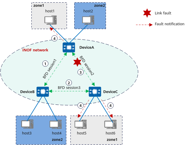
Bidirectional Forwarding Detection (BFD) is used to rapidly detect communication faults between devices and reports faults to upper-layer applications. BFD for iNOF associates BFD with the iNOF protocol so that BFD can notify the iNOF protocol of the detected link faults. The following figure illustrates how BFD for iNOF works.

BFD for iNOF
- In an iNOF system, DeviceA, DeviceB, and DeviceC learn each other's address information through the iNOF protocol. host1 to host6 are connected to the network through DeviceA, DeviceB, and DeviceC. host1, host5, and host6 are added to the iNOF zone zone1 and can communicate with each other.
- DeviceA, DeviceB, and DeviceC establish BFD sessions based on the peer addresses. After BFD sessions are established, BFD starts to detect link faults.
- If the link between DeviceA and DeviceC fails, BFD rapidly detects the fault, sets the status of BFD session 2 to down, and notifies DeviceA and DeviceC of the fault.
- DeviceA and DeviceC notify host1, host5, and host6 in the same iNOF zone of the fault and instruct them to perform a link switchover (from the original optimal link host1 -> DeviceA -> DeviceC -> host5/host6 to host1 -> DeviceA -> DeviceB -> DeviceC -> host5/host6).
Typical Application of iNOF
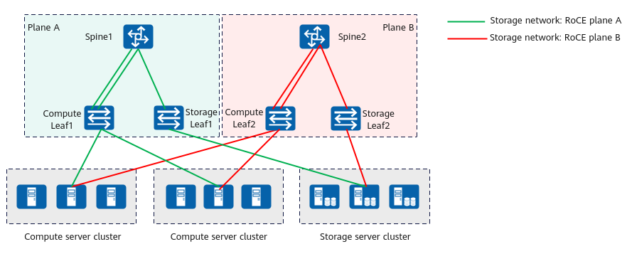
In the three-layer networking of centralized storage, a single DC uses the compute leaf-spine-storage leaf architecture, as shown in the following figure.
To enhance product reliability, a centralized storage cluster adopts two network planes — plane A and plane B — that back up each other. Leaf1 and Leaf2 reside on plane A and plane B, respectively. Leaf nodes function as clients and spine nodes as reflectors in the iNOF system. Leaf nodes only need to be configured to establish iNOF connections with the spine nodes. Other iNOF functions are configured on spine nodes.

Three-layer networking of centralized storage
- Author: Yin Rongrong
- Updated on: 2024-02-27
- Views: 2715
- Average rating:


