What Is M-LAG?
M-LAG technology provides inter-device link aggregation. M-LAG allows two access switches in the same state to perform inter-device link aggregation negotiation with a user-side device or server, improving link reliability from the card level to the device level. In addition, M-LAG devices can be upgraded separately to ensure the stability of service traffic. Therefore, M-LAG is widely used on data center networks.
Why Do We Need M-LAG?
In recent years, M-LAG has been widely used as a virtualization technology, but it is not developed overnight.
On traditional data center networks, redundant devices and links are used to ensure high reliability. To solve problems such as low link utilization and high network maintenance costs, stacking technology is used to virtualize multiple data center switches into one switch, simplifying network deployment and reducing network maintenance costs.
To meet the requirements of growing service traffic and higher network reliability, M-LAG virtualization technology is developed. This technology aggregates links between multiple devices to improve link reliability from the card level to the device level.
STP and VRRP Technologies
STP and VRRP are used on traditional data center networks to ensure link redundancy, meeting basic reliability requirements.
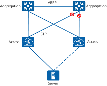
STP+VRRP networking
However, the STP+VRRP solution has the following disadvantages and cannot support the rapid growth in traffic and scale of data center networks.
- The link blocking mechanism of STP causes low Layer 2 link utilization.
- The master/backup function of VRRP causes low Layer 3 link utilization.
- A server can connect to access devices only in active/standby mode.
To overcome the disadvantages of the STP+VRRP solution, stacking and M-LAG virtualization technologies are developed to meet the requirements of growing service traffic and higher network reliability.
Stacking and M-LAG Virtualization Technologies
Stacking and M-LAG technologies implement inter-device link aggregation to improve Layer 2 link utilization. The active-active gateway function of M-LAG improves Layer 3 link utilization. In addition, servers can connect to access devices in active/active mode through link aggregation.
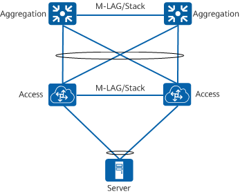
Stacking+M-LAG networking
Both M-LAG and stacking can solve problems on traditional data center networks. However, M-LAG is usually used to ensure service stability.
As two horizontal virtualization technologies that are widely used at the access layer of data center networks, stacking and M-LAG can implement redundant terminal access and link backup, improving the reliability and scalability of data center networks. Compared with stacking, M-LAG has higher reliability and the advantage of separately upgrading each member device.
The following figure compares the advantages and disadvantages of stacking and M-LAG. In scenarios that require a short service interruption time during an upgrade and high network reliability, you are advised to use M-LAG technology as the terminal access technology on your data center network.
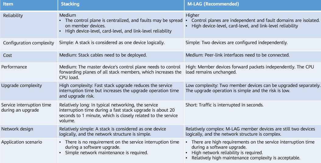
Comparison between stacking and M-LAG
How Do I Establish an M-LAG System?
In an M-LAG system shown in the following figure, inter-device link aggregation is implemented among ServerA, DeviceA, and DeviceB. DeviceA and DeviceB complete M-LAG pairing through a Dynamic Fabric Service Group (DFS group). After DeviceA and DeviceB are successfully paired, they negotiate the master/backup status. After the M-LAG works properly, DeviceA and DeviceB synchronize information with each other in real time through the peer-link. M-LAG fault detection depends on the dual-active detection (DAD) link through which M-LAG member devices periodically send heartbeat packets to each other.
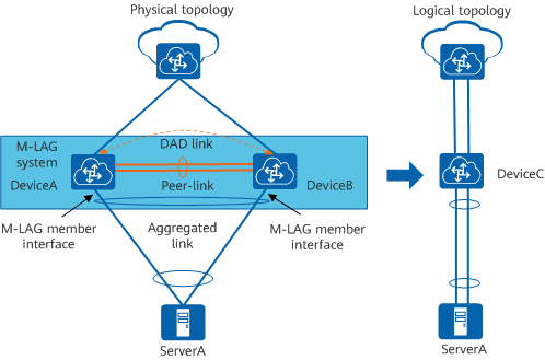
M-LAG networking
The M-LAG implementation process consists of five steps: DFS group pairing, DFS group master/backup negotiation, M-LAG member interface master/backup negotiation, DAD, and M-LAG information synchronization.
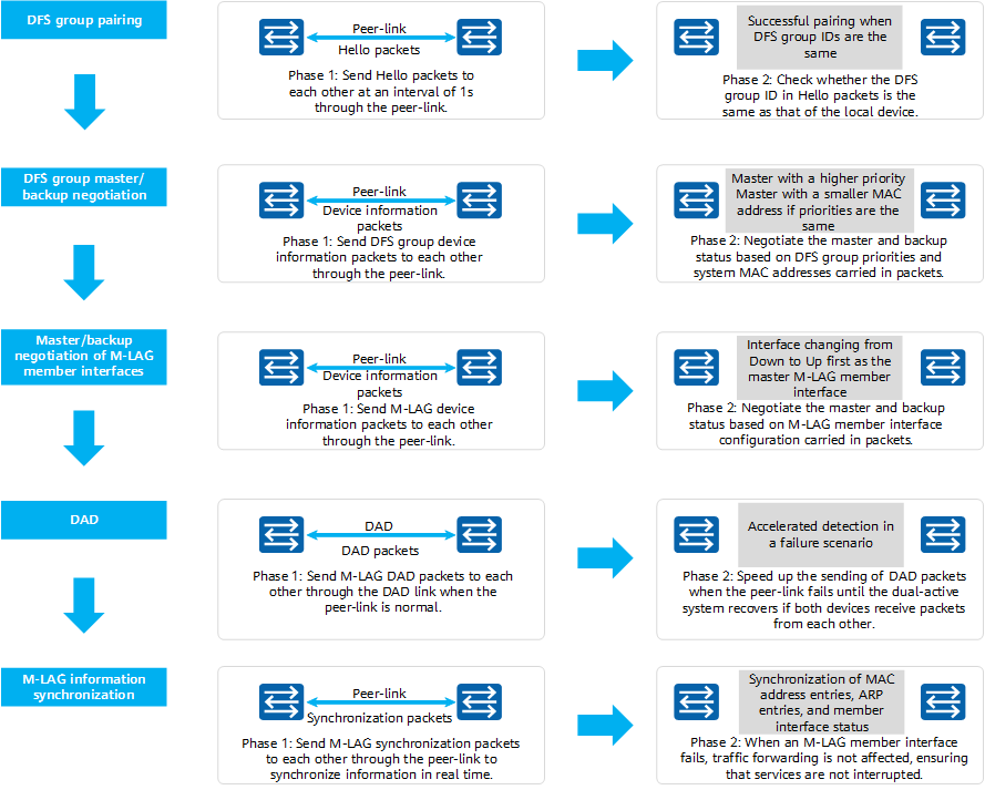
M-LAG implementation
How Does an M-LAG Work?
M-LAG Working Scenarios
- Known Unicast Traffic Forwarding
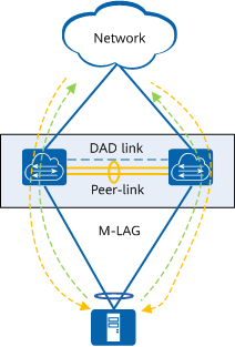
When an M-LAG works properly, known unicast traffic sent from the user side to the network side (marked in green in the figure) is load balanced by M-LAG master and backup devices in per-flow mode. Similarly, known unicast traffic sent from the network side to the user side (marked in yellow in the figure) is also load balanced by M-LAG master and backup devices in per-flow mode.
Known unicast traffic forwarding in an M-LAG - Multicast, Broadcast, and Unknown Unicast Traffic Forwarding
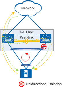
When an M-LAG works properly, multicast, broadcast, and unknown unicast traffic sent from the user side to the network side (marked in yellow in the figure) is flooded between M-LAG devices. To prevent a possible loop (marked in red in the figure), the unidirectional isolation mechanism of M-LAG is used to prevent traffic received by a peer-link interface from being forwarded through an M-LAG member interface. Similarly, when multicast, broadcast, and unknown unicast traffic sent from the network side to the user side (marked in green in the figure) is flooded between devices, the unidirectional isolation mechanism is also used to prevent traffic received by a peer-link interface from being forwarded through an M-LAG member interface.
Multicast, broadcast, and unknown unicast traffic forwarding in an M-LAG
M-LAG Failure Scenarios
- Uplink Failure
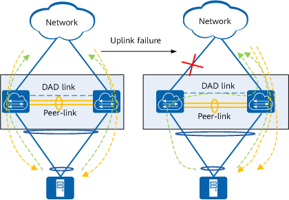
In the following figure, a device is connected to a common Ethernet network through an M-LAG. If the uplink of the M-LAG master device fails, traffic passing through the M-LAG master device is forwarded by the M-LAG backup device through the peer-link. When a device is connected to a Layer 3 network through an M-LAG, a best-effort link must be configured between the M-LAG master and backup devices. Otherwise, the uplink traffic that reaches the master device cannot reach the backup device through the peer-link.
If the faulty link is the DAD link, the M-LAG continues to work properly without being affected. If the peer-link also fails, a dual-active conflict occurs in the M-LAG, and DAD cannot be performed. In this case, traffic sent from the user side to the M-LAG master device is discarded because no uplink interface is available. To solve this problem, you can configure the link between management interfaces as the DAD link, or configure the Monitor Link function to associate the M-LAG member interface with the uplink interface. If the uplink fails, the M-LAG member interface is triggered to go Down, preventing traffic loss.
Traffic forwarding in case of an uplink failure - M-LAG Member Interface Failure
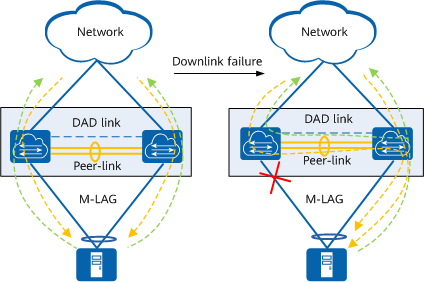
When an M-LAG member interface fails, traffic sent from the user side to the network side (marked in green in the figure) is load balanced between normal links. The network-side device does not detect the fault and still sends traffic to the two M-LAG devices. Because an M-LAG member interface fails, the dual-homing scenario changes to a single-homing scenario. In this case, the interface isolation mechanism does not take effect. When the M-LAG device where the faulty M-LAG member interface resides receives traffic sent from the network side to the user side (marked in yellow in the figure), the device forwards the traffic to the M-LAG device that works properly through the peer-link for forwarding to the user side.
After the faulty M-LAG member interface recovers and goes Up, MAC address entry synchronization is triggered in the M-LAG system. The single-homing scenario is restored to a dual-homing scenario, and traffic is forwarded in load balancing mode.
Traffic forwarding in case of an M-LAG member interface failure - Peer-Link Failure
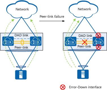
If an M-LAG member device detects that the peer-link is Down, it immediately initiates DAD through the DAD link. If the local device does not receive any DAD packet from the remote device within a specified period, the local device considers that the remote device fails. If the local device receives DAD packets from the remote device, the local device considers that the peer-link fails.
When the peer-link fails, the two M-LAG devices cannot forward traffic at the same time. If they forward traffic at the same time, a broadcast storm or MAC address flapping occurs. Therefore, the M-LAG backup device sets all physical interfaces except the peer-link interface, stack interface, and management interface to Error-Down state. In this case, traffic is forwarded only by the M-LAG master device.
After the faulty peer-link recovers, peer-link interfaces go Up, and M-LAG member devices renegotiate with each other. After the negotiation is complete, all interfaces except M-LAG member interfaces go Up and M-LAG member interfaces go Up 4 minutes later to ensure that the interface isolation mechanism takes effect.
Traffic forwarding in case of a peer-link failure - M-LAG Member Device Failure
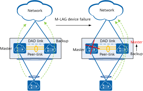
If the M-LAG master device fails, the M-LAG backup device becomes the master device and continues to forward traffic, and its Eth-Trunk link is still in Up state. The Eth-Trunk link of the M-LAG master device goes Down, and the dual-homing scenario changes to a single-homing scenario.
If the M-LAG backup device fails, the master and backup status of M-LAG devices remains unchanged, and the Eth-Trunk link of the M-LAG backup device goes Down. The Eth-Trunk link of the M-LAG master device is still in Up state and continues to forward traffic. The dual-homing scenario changes to a single-homing scenario.
When a faulty M-LAG member device recovers, the peer-link goes Up first, and the two M-LAG member devices renegotiate their master and backup roles. After the negotiation succeeds, the M-LAG member interface on the faulty M-LAG member device goes Up and traffic is load balanced. Both the M-LAG master and backup devices retain their original roles after recovering from a fault.
Traffic forwarding in case of an M-LAG member device failure
What Are the Application Scenarios of M-LAG?
The preceding sections describe the functions of M-LAG, including traffic load balancing and backup protection. Now, let's look at the application scenarios of M-LAG.
M-LAG mainly applies to scenarios where a server or switch is dual-homed to a Layer 2, VXLAN, or Layer 3 network, or to a multi-level M-LAG scenario.
Dual-Homing of a Device to a Layer 2 Network Through an M-LAG
When a device is dual-homed to a Layer 2 network through an M-LAG, the two M-LAG devices need to be virtualized into the same STP logical node to prevent loops.
You can manually configure the two M-LAG devices as STP root bridges or configure the Virtual Spanning Tree Protocol (V-STP) to virtualize them into one STP node. V-STP synchronizes the STP status between M-LAG member devices so that the two devices use the same status for STP negotiation.
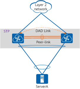
Dual-homing of a device to a Layer 2 network through an M-LAG
Dual-Homing of a Device to a VXLAN Network Through an M-LAG
When a device is dual-homed to a VXLAN network through an M-LAG, the two M-LAG devices need to be virtualized into a VTEP. DeviceA and DeviceB use the IP address of the VTEP to establish a VXLAN tunnel with an external device, regardless of whether the tunnel is manually established or automatically established using MP-BGP.
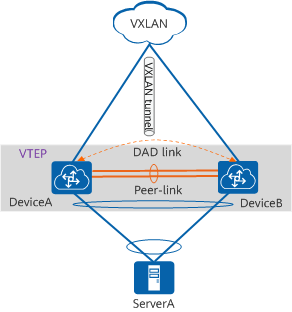
Dual-homing of a device to a VXLAN network through an M-LAG
Dual-Homing of a Device to a Layer 3 Network Through an M-LAG
When a device is dual-homed to a Layer 3 network through an M-LAG, M-LAG member devices are the boundary between the Layer 2 and Layer 3 networks and function as gateways. Because both devices function as gateways, they need to use the same gateway IP address and MAC address for communication with the network-side device. The same IP address and virtual MAC address needs to be configured for DeviceA and DeviceB so that they function as the same gateway.
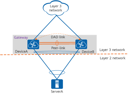
Dual-homing of a device to a Layer 3 network through an M-LAG
Multi-Level M-LAG
On a large network, M-LAG can be deployed on both spine and leaf nodes to ensure link reliability. In the figure, each pair of devices in gray shading establish an M-LAG.
In a multi-level M-LAG scenario, you cannot manually configure the root bridge to prevent STP loops. Instead, you need to use V-STP to synchronize the STP status of member devices in each M-LAG.
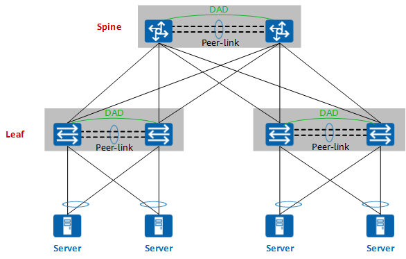
Multi-level M-LAG
- Author: Liu Jieyuan
- Updated on: 2023-04-10
- Views: 17720
- Average rating:


