What Is Plug-and-Play?
Plug-and-play (PnP) is originally a term of computer hardware. In a PnP scenario, when a new external device is connected to a computer, the computer can automatically detect hardware resources without re-configuration or manual driver installation. PnP also refers to hot swapping, meaning that a hardware device, such as a USB device, can be directly connected to or removed from a powered-on computer.
In the data communications field, PnP in network solutions allows network devices and access terminals to automatically access the network upon network connection, saving manual configuration.
Why Is PnP Required on Campus Networks?
As network technologies develop fast and enterprise networks keep expanding, enterprises need to manage and maintain hundreds or even thousands of devices. In the early planning and deployment stages, work such as device installation, configuration, and upgrade takes up one third or even longer of the entire network management and O&M period. In addition, most of the work is simple and repetitive. Therefore, customers are in urgent need of simplified network device installation, deployment management, and software upgrade to further improve efficiency.
In addition, as the Internet of Things (IoT) continues to gain momentum and becomes ingrained in various sectors, more and more terminals of diversified types are connected to campus networks. Especially on large and midsize campus networks, access terminals include not only PCs and mobile phones, but also dumb terminals such as IP phones, printers, and IP cameras, leading to difficult terminal management. With a traditional network management system (NMS), an administrator can only view the IP addresses and MAC addresses of access terminals, but cannot perform refined terminal management. To plan and deploy different network services and policies for different types of terminals, the administrator needs to perform manual configuration. This results in complex service deployment and operations. As such, automatic identification and PnP of terminals become a must.
The next-generation PnP solution simplifies the network installation process. The SDN controller in the solution provides networks with automatic deployment capabilities, and seamlessly combines pre-deployment planning and subsequent network maintenance. This largely improves network management and O&M efficiency and reduces labor and time costs. The solution has the following advantages:
- Visualization: Network administrators and installation engineers can perform operations on the graphical user interface (GUI), with configuration and network planning all visualized.
- High efficiency: Services are deployed on the SDN controller (such as Huawei iMaster NCE-Campus) in advance, shortening the end-to-end deployment process from several days to only several hours.
- Accuracy: All configurations are performed on the SDN controller's GUI, which is less error-prone compared with CLI-based configuration. Wrong cable connections can be presented on the GUI in real time, facilitating fast troubleshooting.
How Does PnP Work on Network Devices?
Take switches as an example. A cloud campus network with hierarchical tree structure has a large number of aggregation and access switches below the core layer. Implementing PnP on such switches greatly improves deployment efficiency and reduces deployment workload.
After interconnecting with the SDN controller using commands, the core switch is configured as the root device of the management subnet, and then switches below the core layer go online on the SDN controller in PnP mode using a DHCP option.

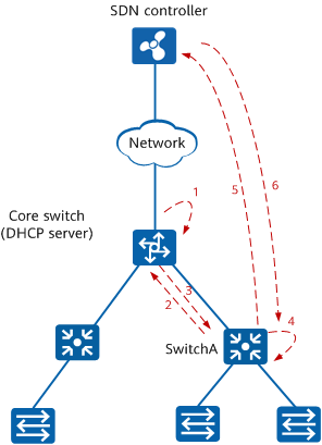
PnP of switches
As shown in the preceding figure, the PnP process of aggregation switch SwitchA is as follows:
An administrator configures the DHCP server function on the core switch or deploys an independent DHCP server on the network, enables the DHCP function on VLANIF 1, and configures DHCP Option 148, which contains the NETCONF enabling status as well as the URL/IP address and port number of the SDN controller.
After SwitchA starts up with no configuration, it sends a DHCP request packet using VLANIF 1 to the DHCP server by default.
Before delivery, all interfaces of a switch are added to VLAN 1 by default. Therefore, the core switch can communicate with SwitchA in VLAN 1.
After receiving the request packet, the core switch that functions as a DHCP server replies to SwitchA with a DHCP response packet containing DHCP Option 148.
Based on the Option 148 field contained in the received DHCP response packet, SwitchA enables NETCONF and obtains the URL/IP address and port number of the SDN controller.
SwitchA uses the obtained URL/IP address and port number of the SDN controller to register with the SDN controller.
- After SwitchA registers with the SDN controller and goes online, the SDN controller automatically delivers the pre-configurations (including the PnP VLAN) configured by the administrator to SwitchA. As such, SwitchA is deployed using PnP.
PnP VLAN
PnP VLAN, also called auto-negotiated management VLAN, is a key concept in the PnP process of network devices. It is used for the SDN controller to manage switches or APs.
By default, aggregation and access switches use VLAN 1 to register with and go online on the SDN controller. However, as the default PVID of all switch interfaces, VLAN 1 is prone to broadcast storms that affect services and is typically not used as the management VLAN, as a way to improve network reliability. Therefore, the administrator needs to configure another management VLAN, named PnP VLAN, on the SDN controller. After going online using VLAN 1, aggregation and access switches automatically switch to this management VLAN.
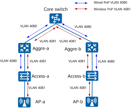
To facilitate network maintenance on campus networks, wired and wireless networks usually use different PnP VLANs, that is, wired PnP VLAN and wireless PnP VLAN. Switches use the wired PnP VLAN, while APs use the wireless PnP VLAN.

PnP VLAN
The PnP VLAN switching process is as follows:
- Aggregation and access switches use VLAN 1 to register with and go online on the SDN controller.
- The SDN controller delivers the pre-configured PnP VLAN to the aggregation and access switches.
- The aggregation and access switches use the negotiated PnP VLAN to register with and go online on the SDN controller again, implementing PnP.
How Does PnP Work on Access Terminals?
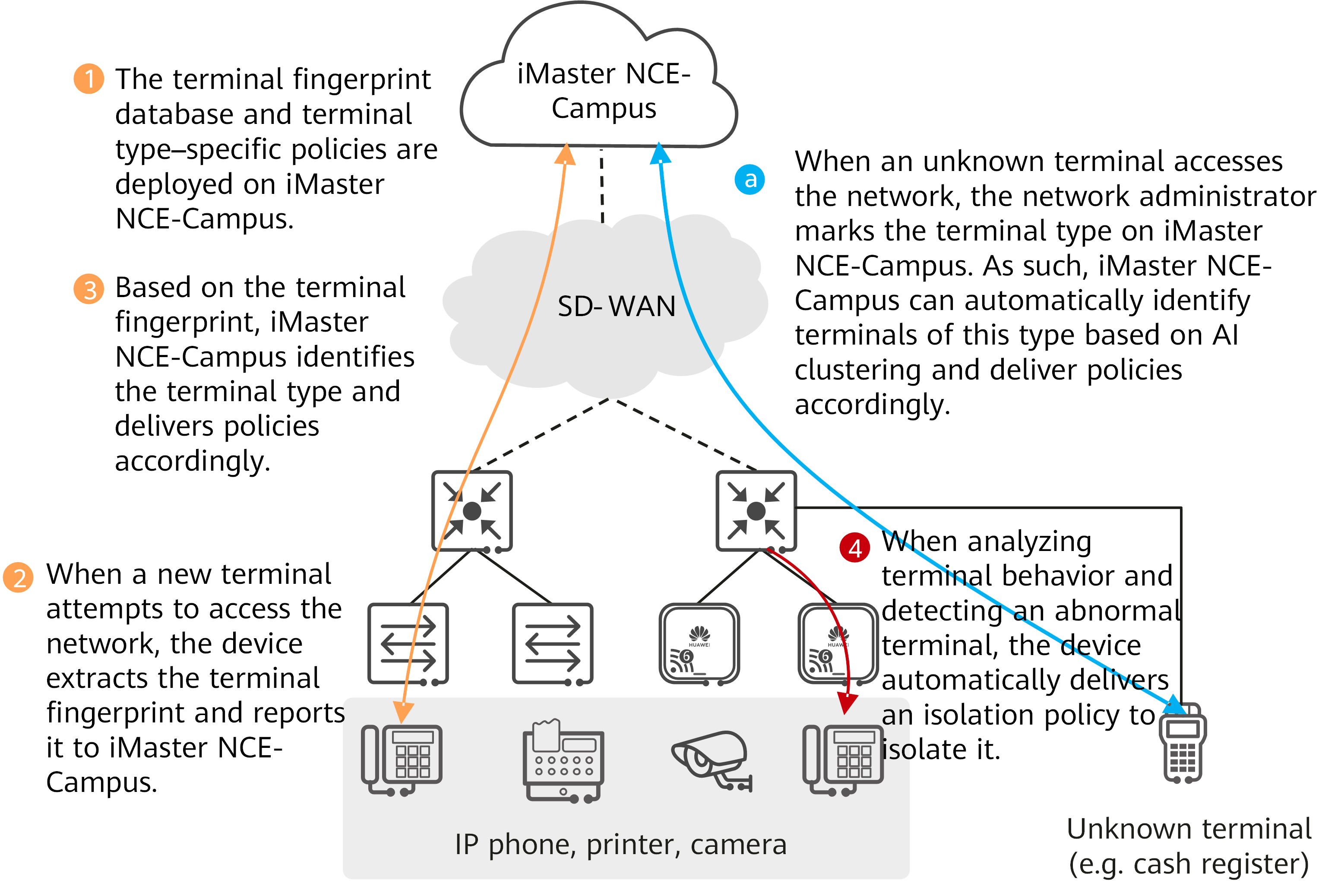
The following figure shows the PnP process of terminals, including terminal identification and terminal anomaly detection.

PnP of terminals
- The network O&M personnel deploy the terminal fingerprint database and terminal type–specific policies on iMaster NCE-Campus in advance.
- When a terminal attempts to access the network, the network device automatically collects the terminal's fingerprint and reports it to iMaster NCE-Campus.
- iMaster NCE-Campus identifies the terminal type based on the fingerprint, and delivers policies accordingly, implementing PnP and improving terminal access efficiency.
- When a terminal of an unknown type accesses the network, the network administrator can mark the terminal type on iMaster NCE-Campus. In this way, terminals of this type can be automatically identified and allowed onto the network through AI clustering. After terminals are connected to the network, devices intelligently analyze the terminals' traffic in real time. When devices detect that the traffic of some terminals is too heavy or duplicate terminal IP addresses or MAC addresses exist, the devices automatically deliver isolation policies to the involved abnormal terminals.
- Author: Gu Suqin
- Updated on: 2023-09-01
- Views: 3111
- Average rating:


