What Is CSC?
Carrier's Carrier (CSC) is a networking solution in BGP/MPLS IP VPN. In this solution, the users of a carrier are also carriers. The Level 1 carrier's CE advertises only the Level 2 carrier's internal routes, not the Level 2 carrier's customer routes, to the Level 1 carrier's PE.
CSC reduces the number of routes that need to be maintained on the Level 1 carrier's network and simplifies operations. Moreover, it allows the Level 1 carrier to provide unified configuration, management, and maintenance for Level 2 carriers, reducing their operation burdens.
Why Do We Need CSC?
Multiprotocol Label Switching (MPLS), a tunneling technology widely deployed on global networks, needs to adapt to various complex service scenarios. Different metro networks of a carrier or different carrier backbone networks that interwork with each other often belong to different ASs. To solve the problem of complex information exchange brought by inter-AS routing information transmission, inter-AS VPN and CSC solutions are introduced. The CSC solution adopts a hierarchical VPN model. As shown in the following figure, it allows a service provider's user to be another service provider. The former service provider is called a provider carrier or a Level 1 carrier, and the latter service provider is called a customer carrier or Level 2 carrier. The Level 1 carrier allows Level 2 carriers to be BGP/MPLS IP VPN service providers. Level 2 carriers can interwork through the MPLS backbone network, facilitating the OAM of both Level 1 and Level 2 carriers.
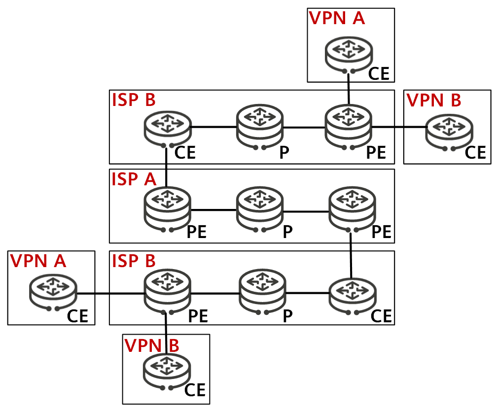
CSC networking
Benefits to Level 1 Carriers
CSC offers the following benefits to a Level 1 carrier:
- The Level 1 carrier allows multiple Level 2 carriers to access the same backbone network. This eliminates the need to create and maintain a separate backbone network for each Level 2 carrier, lowering maintenance costs, simplifying management operations, and improving management efficiency.
- The Level 1 carrier can use one backbone network to provide VPN and Internet services for multiple Level 2 carriers, increasing revenues.
Benefits to Level 2 Carriers
CSC offers the following benefits to a Level 2 carrier:
- The Level 2 carrier can reduce its own burdens by delegating configuration, management, and maintenance operations to the Level 1 carrier.
- The Level 2 carrier can flexibly plan addresses, because its addresses are independent of those of its customers and the Level 1 carrier.
- The Level 2 carrier can be either an ISP or BGP/MPLS IP VPN service provider, and its unique requirements for security and bandwidth can be met.
What CSC Solutions Are Available?
- The Level 2 carrier's internal and customer routes are called internal and external routes for short, respectively.
- The Level 1 carrier's CEs refer to the devices used by the Level 2 carrier to access the Level 1 carrier network. These devices function as CEs for the Level 1 carrier and as PEs for the Level 2 carrier. The devices used by users to access the Level 2 carrier network are called user CEs.
Level 2 Carrier Being an ISP
When the Level 2 carrier is an ISP, the networking is equal to overlaying an IP network onto a BGP/MPLS IP VPN. The Level 2 carrier's PEs does not need to provide MPLS functions and only need to use an IGP to communicate with the Level 1 carrier's CEs. In this case, the Level 2 carrier's PEs (CE1 and CE2) exchange internal routes through BGP sessions, as shown in the following figure.

Level 2 carrier being an ISP
In this scenario, if CE1 and CE2 belong to the same AS, an IBGP peer relationship needs to be established between them. Moreover, CE1 and CE2 can be configured as route reflectors (RRs). If CE1 and CE2 belong to different ASs, an EBGP peer relationship needs to be established between CE1 and CE2.
Level 2 Carrier Being a BGP/MPLS IP VPN Service Provider
If the Level 2 carrier is a BGP/MPLS IP VPN service provider, its PEs need to provide MPLS functions and use an IGP and LDP to communicate with the Level 1 carrier's CEs. The Level 2 carrier's PEs (PE3 and PE4) exchange external routes through MP-BGP sessions, as shown in the following figure.

Level 2 carrier being a BGP/MPLS IP VPN service provider
In this scenario, PE3 and PE4 need to provide VPN services and therefore need to have LSPs established between them. The Level 1 and Level 2 carrier networks generally run LDP internally. The solution for Level 1 carrier's CEs to access Level 1 carrier's PEs can be further classified into the following two types:
- Solution with LDP LSPs being established using LDP multi-instance
- Solution with BGP LSPs being established using labeled BGP routes
How Does CSC Work?
Level 2 carriers are rarely ISPs and the corresponding solution deployment is relatively simple. Instead, they are often BGP/MPLS IP VPN service providers in live network scenarios. As such, the following describes in detail the two modes in which Level 1 carrier's CEs access Level 1 carrier's PEs for scenarios with Level 2 carriers being BGP/MPLS IP VPN service providers.
LDP Multi-instance-based CSC Solution
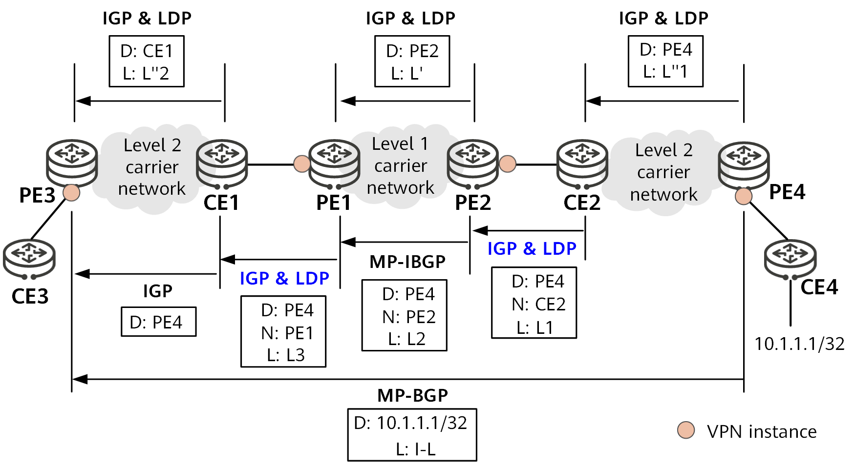
The following figure shows how routing information is exchanged when the Level 1 carrier's CEs access the Level 1 carrier's PEs over LDP LSPs established using LDP multi-instance. Here, D represents the destination address of a route, N the next hop, and L the label.
Routing information exchange based on LDP multi-instance
Use the advertisement of VPN route 10.1.1.1/32 from PE4 to PE3 as an example. The routing information is exchanged between the Level 2 carrier's PEs as follows:
PE4 advertises the route destined for itself to CE2 through the IGP running on the Level 2 carrier network, assigns label L''1 to the route locally, and establishes a public network LSP with CE2.
CE2 advertises the route destined for PE4 to PE2 through the IGP running between itself and PE2. At the same time, CE2 assigns label L1 to the route locally through LDP. Here, LDP multi-instance must be configured on the PE2 interface connected to CE2.
PE2 assigns label L2 to the route destined for PE4 and advertises the route and label to PE1 through MP-IBGP. Previously, PE2 has advertised routes destined for itself to PE1 through the IGP running on the Level 1 carrier's backbone network, assigned public network label L' to these routes locally, and established a public network LSP with PE1.
PE1 assigns label L3 to the route destined for PE4 over the LDP multi-instance peer relationship with CE1 and advertises the route and label to CE1.
CE1 advertises the route destined for PE4 to PE3 through the IGP. Previously, CE1 has advertised routes destined for itself to PE3 through the IGP running on the Level 2 carrier's backbone network, assigned label L''2 to these routes locally, and established a public network LSP with PE3 on the Level 2 carrier network.
The process of advertising the route destined for PE4 to PE3 is then complete. After the routing information of PE3 is advertised to PE4 in a similar way, an MP-IBGP connection can be successfully established between PE3 and PE4.
PE4 assigns VPN label I-L for the VPN route destined for 10.1.1.1/32 to PE3 over the MP-IBGP connection.
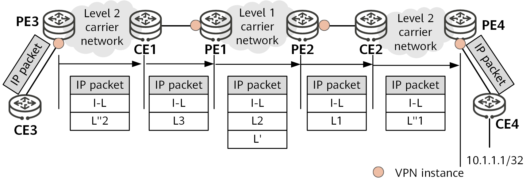
The following figure shows how a VPN packet is transmitted on carrier networks. Here, I-L indicates the VPN label assigned by MP-BGP, L' the public network label used on the Level 1 carrier network, and L''1 and L''2 the public network labels used on the Level 2 carrier network. L1, L2, and L3 represent labels assigned to packets destined for PE4.
Packet forwarding based on LDP multi-instance
The following uses the forwarding of a VPN packet destined for 10.1.1.1/32 from PE3 to CE4 as an example to describe how a VPN packet is forwarded on carrier networks:
After receiving the VPN packet destined for 10.1.1.1/32, PE3 adds VPN label I-L and public network label L''2 to the packet and then transparently transmits the packet to CE1 over the public network LSP on the Level 2 carrier network. Before the packet arrives at CE1, the penultimate LSR removes public network label L''2.
CE1 adds label L3 to the packet and forwards the packet to PE1.
PE1 replaces label L3 with label L2, adds public network label L' to the packet, and forwards the packet to PE2 over a public network LSP on the Level 1 carrier network. Before the packet arrives at PE2, the penultimate LSR removes public network label L'.
PE2 replaces label L2 with label L1 and forwards the packet to CE2.
CE2 removes label L1 from the packet, adds public network label L''1 to the packet, and transparently transmits the packet to PE4 over a public network LSP on the Level 2 carrier network. Before the packet arrives at PE4, the penultimate LSR removes public network label L''1.
PE4 removes VPN label I-L from the packet and forwards the packet to CE4 based on label I-L.
BGP Labeled Route-based CSC Solution
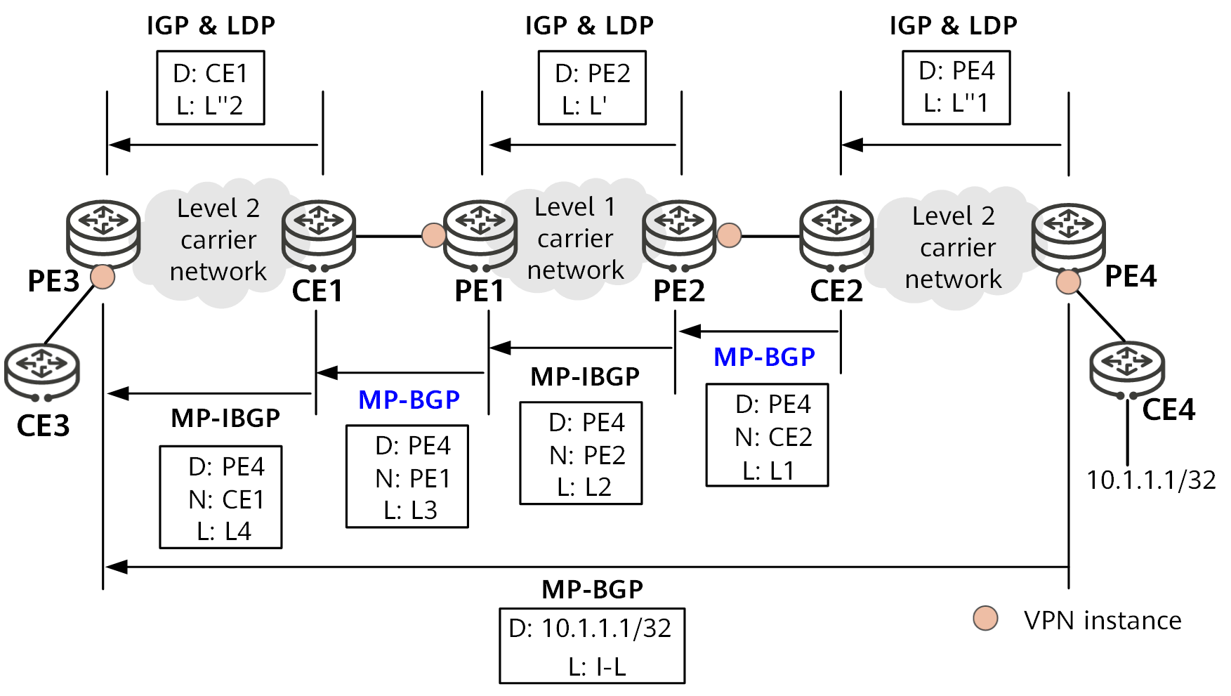
The following figure shows how routing information is exchanged when the Level 1 carrier's CEs access the Level 1 carrier's PEs over BGP LSPs established using BGP labeled routes. Here, D represents the destination address of a route, N the next hop, and L the label.
Routing information exchange based on BGP labeled routes
Use the advertisement of VPN route 10.1.1.1/32 from PE4 to PE3 as an example. The routing information is exchanged between the Level 2 carrier's PEs as follows:
PE4 advertises the route destined for itself to CE2 through the IGP running on the Level 2 carrier network, assigns label L''1 to the route locally, and establishes a public network LSP with CE2.
CE2 assigns label L1 to the route destined for PE4 based on the MP-BGP peer relationship with PE2 and advertises the route and label to PE2.
PE2 assigns label L2 to the route destined for PE4 and advertises the route and label to PE1 through MP-IBGP. Previously, PE2 has advertised routes destined for itself to PE1 through the IGP running on the Level 1 carrier's backbone network, assigned label L' to these routes locally, and established a public network LSP with PE1.
PE1 assigns label L3 to the route destined for PE4 over the MP-BGP peer relationship with CE1 and advertises the route and label to CE1.
CE1 assigns label L4 to the route destined for PE4 and advertises the route and label to PE3 over the MP-IBGP peer relationship with PE3. Previously, CE1 has advertised routes destined for itself to PE3 through the IGP running on the Level 2 carrier's backbone network, assigned public network label L''2 to these routes locally, and established a public network LSP with PE3 on the Level 2 carrier network.
The process of advertising the route destined for PE4 to PE3 is then complete, and a BGP LSP is established between CE2 and PE3. After the routing information of PE3 is advertised to PE4 in a similar way, an MP-IBGP connection can be successfully established between PE3 and PE4.
PE4 assigns VPN label I-L for the VPN route destined for 10.1.1.1/32 to PE3 over the MP-EBGP connection.
The following figure shows how a VPN packet is transmitted on carrier networks. Here, I-L indicates the VPN label assigned by MP-BGP, L' the public network label used on the Level 1 carrier network, and L''1 and L''2 the public network labels used on the Level 2 carrier network. L1, L2, L3, and L4 represent labels assigned to packets destined for PE4.
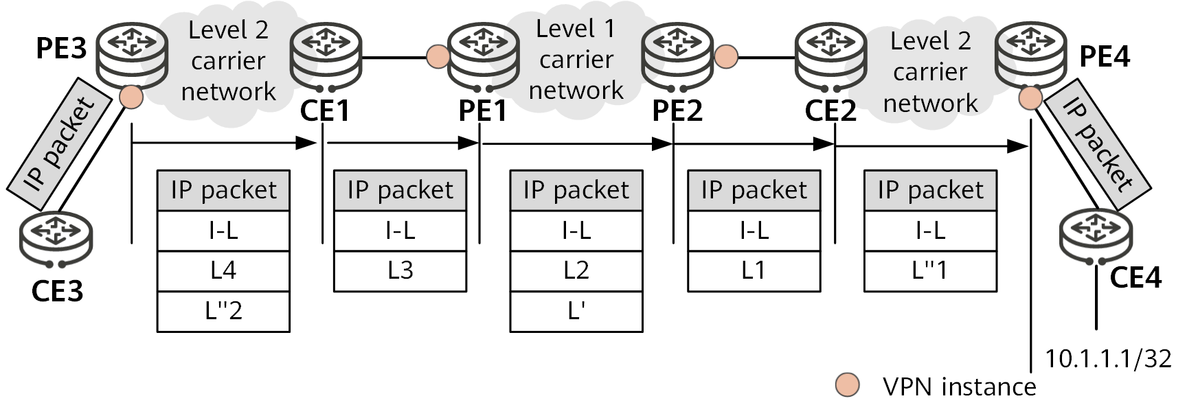
Packet forwarding based on BGP labeled routes
The following uses the forwarding of a VPN packet destined for 10.1.1.1/32 from PE3 to CE4 as an example to describe how a VPN packet is forwarded on carrier networks:
After receiving the VPN packet destined for 10.1.1.1/32, PE3 adds VPN label I-L, BGP LSP label L4, and public network label L''2 to the packet and then transparently transmits the packet to CE1 over the public network LSP on the Level 2 carrier network. Before the packet arrives at CE1, the penultimate LSR removes public network label L''2.
CE1 replaces label L4 with label L3 and forwards the packet to PE1.
The remaining packet forwarding process is similar to that based on LDP multi-instance.
- Author: Chen Jingyi
- Updated on: 2024-01-18
- Views: 6480
- Average rating:


