What Is SPN?
SPN is a next-generation converged transport network architecture that inherits, enhances, and innovates the packet transport network (PTN) technology. Proposed by China Mobile, Huawei, and other equipment vendors for 5G transport, this innovative technological system is designed with slicing Ethernet (SE) at the core. Its technical advantages include being able to provide low latency, high bandwidth, ultra-precise synchronization, and flexible management and control. Furthermore, it is compatible with the Ethernet ecosystem and features low cost and easy deployment.
Why Do We Need SPN?
As new and diversified services emerge in the 5G and cloud era, different industries, services, and users place higher requirements on the bandwidth, latency, reliability, and other performance indicators of transport networks. These networks must be able to provide various functions — such as flexible traffic scheduling, networking protection, management, and control — and assure performance in terms of bandwidth, latency, synchronization, and reliability, among others. PTN cannot meet these transport requirements of 5G services. To address this, China Mobile, Huawei, and other equipment vendors proposed SPN, an Ethernet-based next-generation converged transport network architecture that integrates packet, transport, optical-layer, and other technologies.
Using the Ethernet transmission architecture, SPN inherits, enhances, and innovates the functions of the PTN transport solution. SPN adds a lightweight TDM layer to the Ethernet physical (PHY) layer. In this way, packet devices can provide network slicing capabilities (namely, hard isolation and deterministic low-latency) without needing modification of the current packet technologies. SPN has attracted worldwide attention and support from the industry not only because it supports packet and TDM convergence, low latency, and network slicing, but also because it is compatible with the ecosystem and can significantly reduce costs. The ITU-T officially approved the G.mtn project in October 2018 — indicating that the slicing Ethernet (SE) technology is reaching maturity driven by SPN — and accepted the core concept and technical architecture of SE.
SPN enhances and innovates PTN in multiple ways, as described in the following table.
Network Layer |
Major Function |
PTN |
SPN |
Enhancement/Innovation |
|---|---|---|---|---|
L2 and L3 packet forwarding layers |
Network connection, OAM, protection, statistical multiplexing, and QoS assurance. |
Multi-Protocol Label Switching Transport Profile (MPLS-TP) |
SR-TP Segment Routing-Best Effort (SR-BE) |
SPN uses SR-TP to provide manageable and controllable L3 tunnels and to construct an E2E L3 service deployment model. It introduces an L3 control plane that features centralized management and control. Through the Software-Defined Networking (SDN) platform that converges management and control functions, SPN logically abstracts and virtualizes NEs' physical resources (such as forwarding, computing, and storage resources) to form a virtual network on demand. As such, SPN is able to present a network model with multiple networking architectures for a single physical network. In this way, users are provided with an open, flexible, and efficient network operating system. |
L1 TDM channel layer |
TDM channel isolation, scheduling, multiplexing, OAM, and protection. |
TDM channel |
SE path |
This layer provides hard pipe isolation required by network slicing to ensure low latency. In SPN, this layer is called the slicing channel layer (SCL). |
L1 data link layer |
Adapts L1 channels to the optical layer. |
Ethernet |
Ethernet and Flexible Ethernet (FlexE) |
SPN introduces FlexE interfaces to decouple service rates from physical channel rates based on Ethernet. The physical interface rates no longer need to be equal to client service rates; instead, they can be defined flexibly. |
L0 optical transmission layer |
Provides optical interfaces or multi-wavelength transmission, grooming, and networking. |
Gray light or DWDM colored light |
Gray light or DWDM colored light |
SPN introduces Four-Level Pulse Amplitude Modulation (PAM4) for Ethernet gray light, and Wavelength Division Multiplexing (WDM) to reduce the transmission costs of metro and local networks. |
What Are the Advantages of SPN?
SPN Architecture
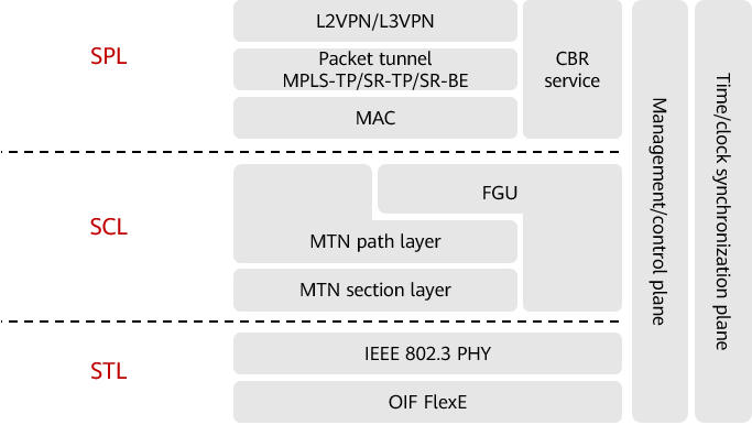
Like the ITU-T network model, the SPN architecture is also layered. As shown in the following figure, the SPN architecture mainly consists of the slicing packet layer (SPL), SCL, and slicing transport layer (STL). It also includes two planes — the management/control plane and the time/clock synchronization plane.
- The SPL implements addressing, forwarding, and transport pipe encapsulation for IP, Ethernet, and constant bit rate (CBR) services. It also supports multiple service types such as L2VPN, L3VPN, and CBR transparent transmission. Based on multiple addressing mechanisms, such as IP, MPLS, 802.1Q, and physical interface protocols, the SPL maps services and provides service identification, traffic distribution, and QoS assurance.
- The SCL provides E2E channelized hard isolation for network services and slices. It uses the innovative SE technology to implement timeslot processing for Ethernet physical interfaces and FlexE groups, providing E2E Ethernet-based virtual network connection capabilities. It also provides L1-based low-latency and hard-isolation slicing channels for multi-service transport. Additionally, this layer supports the use of OAM and protection functions for SE paths, enabling E2E performance monitoring and fault rectification.
- The STL enables efficient large-bandwidth transmission based on IEEE 802.3 Ethernet physical-layer technologies and Optical Internetworking Forum (OIF) FlexE technologies. The OIF FlexE PHY layer supports new high-speed Ethernet interfaces such as 50GE, 100GE, 200GE, and 400GE. Leveraging the near-ubiquitous Ethernet ecosystem, low-cost and high-bandwidth networks can be constructed, and mainstream networking modes with a single hop of up to 80 km are supported.
- The management/control plane supports the provision of SDN management and control capabilities, flexible configuration of services and network resources, and automatic and intelligent network O&M capabilities.
- The time/clock synchronization plane supports the deployment of high-precision clock sources on core nodes and the provision of IEEE 1588v2-based high-precision time synchronization transport capabilities. This makes it possible to meet the requirements of basic and collaborative 5G services for high-precision time synchronization.
SPN architecture
Ultra-High Bandwidth Transmission
As services require ever more bandwidth, transport networks urgently need new technologies. One such technology is SPN, which thanks to it integrating the high-speed Ethernet interface technology with the DWDM multi-wavelength technology, can provide ultra-large bandwidth.
Ethernet is a widely used interface technology in the communications field. Thanks to the development of the Internet, high-speed Ethernet interfaces have made great progress in recent years to keep up with the growth of service bandwidth. To achieve flexible rate matching, FlexE decouples the MAC and PHY layers by introducing a FlexE shim layer on the basis of IEEE 802.3. A FlexE interface can function as a new high-speed Ethernet interface, such as 50GE, 100GE, 200GE, or 400GE, facilitating low-cost and high-bandwidth network construction while also meeting high-bandwidth requirements.
High-speed Ethernet interfaces involve the following key technologies:
- Fast EtherChannel (FEC): implements long-distance transmission through the mature KP4 FEC.
- PAM4: doubles the data rate without changing the baud rate, reducing the cost of optical interfaces.
SPN integrates FlexE bonding and DWDM to flexibly expand and divide transport network bandwidth. FlexE bonds multiple optical interfaces to provide high-speed Ethernet interfaces at a low cost. The maximum bandwidth that a FlexE link can provide is determined by how many interfaces are bonded into a FlexE group. For example, four 200GE Ethernet interfaces can be bonded to provide 800GE bandwidth. This means that FlexE bonding can smoothly expand link bandwidth without the need for service adjustment — the more interfaces that can be bundled into a FlexE group on a device, the greater the network scalability. In addition to providing high bandwidth for single fibers, FlexE and DWDM support smooth bandwidth expansion on demand when working with DWDM channels.
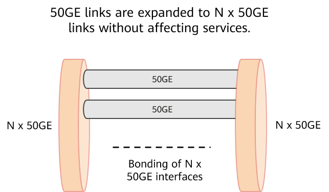
FlexE bonding technology
Low-Latency and Reliable Transport
Ultra-low latency is essential for 5G services. For example, eMBB services require a maximum E2E latency of 10 ms, and URLLC services require even lower E2E latency. However, when service packets are forwarded on a traditional packet network, queuing is often employed in the outbound direction, leading to high latency that can reach tens of microseconds (μs). If the network is congested, the latency may even exceed 10 ms, which is far too long for latency-sensitive 5G services.
FlexE packet slicing solves this problem. Given that traditional interface scheduling is based on packet priorities, low-priority long packets may block high-priority short packets, leading to service interference. FlexE packet slicing replaces the original packet-by-packet transmission mechanism with the strict TDM scheduling mechanism. This timeslot-based scheduling ensures that channels occupy exclusive bandwidth and that private networks are used for dedicated purposes. In this way, services are strictly isolated from each other, improving service security. Defined by OIF, FlexE provides interface-level slicing capabilities. And by leveraging FlexE, G.mtn (defined by the ITU-T) enhances OAM and cross-connect features as SPN continues to develop. G.mtn supports both interface- and channel-level slicing capabilities.

Channelization of FlexE packet slicing
Efficient and Flexible Slices
With the emergence of diversified services in the 5G and cloud era, different industries, services, and users pose various service performance requirements on networks. And because transport networks need to carry services of numerous industries, many emerging industries need to be isolated through network slicing — this is necessary to reduce the impact of service rollout on the entire network and trial-and-error costs. FlexE, which is formulated by OIF, provides a mechanism for logical slice isolation based on Ethernet physical interfaces. However, it still lacks SLA isolation for E2E services. To resolve this issue, MTN is proposed in the SPN technical architecture. MTN slicing, extended based on the native Ethernet, is fully compatible with the current IEEE-defined Ethernet ecosystem. Furthermore, it enables Ethernet L1 networking, which not only provides deterministic low latency and hard pipe isolation capabilities, but also eliminates the need for packets to be buffered and forwarded at L2 or L3.
MTN uses the following key technologies:
- Timeslot cross-connect based on Ethernet 64B/66B blocks: achieves low latency and transparent transmission while also ensuring hard isolation.
- On-demand E2E OAM: uses idle block replacement in IEEE 802.3 block extension to implement OAM and protection for SE paths, supporting E2E Ethernet L1 networking.
- Transparent mapping for Ethernet services: transparently maps various services to SE paths for transmission through the transcoding mechanism.
SPN provides both highly reliable hard slicing (using MTN TDM channels) and scalable soft slicing (using SR over Ethernet packet switching channels and QoS technology) capabilities. Specifically, hard slicing provides low latency and bandwidth assurance for private line and URLLC services, among others, and soft slicing provides high bandwidth and differentiated SLA assurance for packet services such as eMBB.
As shown in the following figure, slices can be implemented as follows:
- Default slice: DSCP priorities can be adjusted to ensure that high-priority packets are preferentially forwarded. This type of slice applies to users who have low slicing requirements.
- Packet+MTN interface slices (shared TDM slices): Different L3VPN slice users are isolated by VPNs and offered bandwidth through CIR. This type of slice applies to users who have high slicing requirements.
- MTN channel slices: E2E hard slicing channels with exclusive resources are used to provide TDM isolation, ultra-low latency, and bandwidth assurance. This type of slice applies to users who have high slicing requirements.
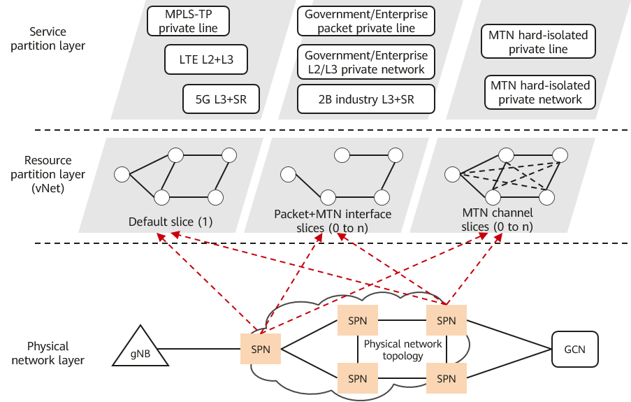
Slicing implementation
Optimized SDN-based Centralized Management and Control
SPN employs the SDN concept to realize open, flexible, efficient, and automatic network O&M. In addition to supporting automatic service deployment, SPN can monitor network status to automatically optimize the network in real time. The following figure shows that SPN is evolving towards intelligent management and control on a platform that integrates management, control, and analysis.
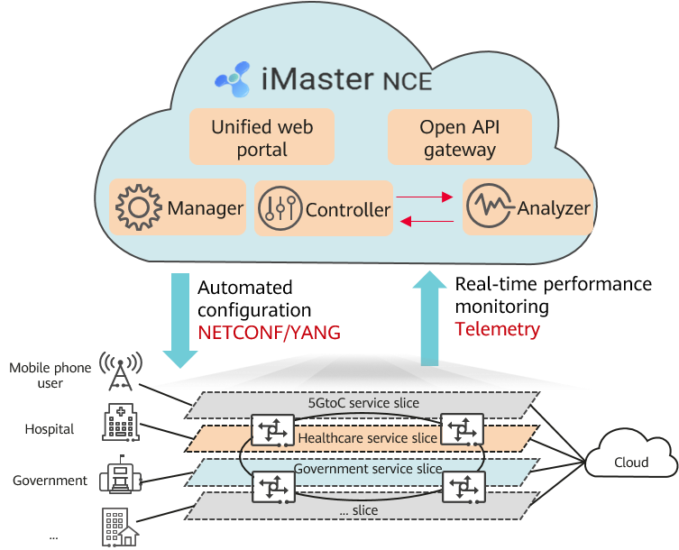
Intelligent management and control platform
On an SPN, management, control, and analysis functions are implemented as follows:
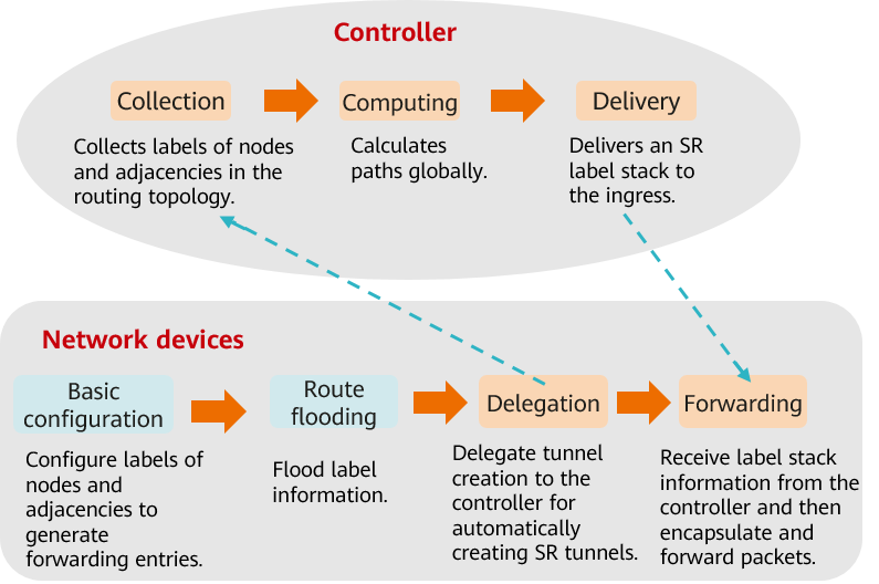
- Management: An SDN controller works together with devices to automatically deploy and optimize services. Node and adjacency labels are configured on network devices to generate forwarding entries. Label information is then flooded and delegated to the controller so that it can automatically create SR tunnels. After the controller collects the route topology information and labels of each node and adjacency, it computes paths globally and delivers an SR label stack to the ingress. Upon receipt, the ingress encapsulates and forwards the packets.
SDN controller and device responsibilities - Control: SR-TP rerouting protects the network against multiple points of failure, ensures that services are always online, and implements flexible and reliable connections. In the past, both the working and protection paths were linear one, meaning that if both paths failed, services would be interrupted. This would require quick fault locating and service repair (involving high maintenance costs). Furthermore, routes would need to be manually adjusted in the repair process, resulting in low efficiency. NCE provides real-time path control capabilities for SR-TP tunnels, including rerouting during SR-TP tunnel path computation and protection. Such capabilities ensure that, if both the working and protection paths fail, rerouting is triggered on the control plane to compute a new best-effort path. In this way, sub-second restoration of services is achieved, ensuring service continuity. For more information about SR-TP, see SR-TP tunnel.
- Analysis: Traditional TP OAM out-of-band measurement can be performed either indirectly or directly. Indirect measurement uses simulated rather than real service data, meaning that the constructed service path may not reflect the real service situation. Direct measurement inserts measurement packets into service flows for tunnel-level measurement. However, it does not support service-level measurement, and measurement precision is low because packets are sent at intervals. Both measurement methods have their drawbacks. In-situ Flow Information Telemetry (IFIT) overcomes these drawbacks by directly measuring real packets, enabling the real path and latency information to be reflected. It can also measure packets one by one to accurately detect minor packet loss, implementing service-level SLA visualization.
Where Is SPN Used?
Smart Mining Service
As the coal mine industry evolves towards intelligence, higher and higher performance requirements are imposed on coal mine networks. A coal mine typically operates multiple underground networks. Production services such as remote monitoring and remote operation need hard isolation to ensure independent bandwidth for each service. Furthermore, due to the special characteristics of the underground environment, device maintenance is difficult, meaning that the underground networks must be highly reliable. Otherwise, if a network fault occurs, O&M personnel need to troubleshoot by removing and reinserting ports one by one, severely lowering the production efficiency of coal mine operations. In addition, multiple underground networks run concurrently and involve many maintenance points, pushing up the network construction cost. On top of all these issues is the inability of current networks to provide sufficient bandwidth to support the large-scale deployment of HD cameras. This is why SPN provides the intelligent slicing solution that features fixed-mobile convergence (FMC). This solution ensures high bandwidth, low latency, and high reliability of coal mine networks.
- 50GE devices are deployed underground to form an access ring, and FlexE slicing is performed on 50GE links to build an ultra-broadband infrastructure network.
- Core SPN devices above-ground in the mining area interconnect with the core network and system platforms through different interfaces. Specifically, these SPN devices are deployed in the multi-access edge computing (MEC) equipment room and use different physical interfaces to connect to the User-Network Interfaces (UNIs) of the MEC node, security supervision system, remote control system, and video surveillance system.
- In addition to connecting to the MEC node, a pair of SPN devices (core nodes 1 and 2 in the mining area shown in the following figure) also connect to the above- and below-ground access rings, and function as common aggregation nodes of the metro SPN transport network.
- Base station Baseband Units (BBUs) and SPN devices are deployed in the same equipment room, reducing equipment room investment.
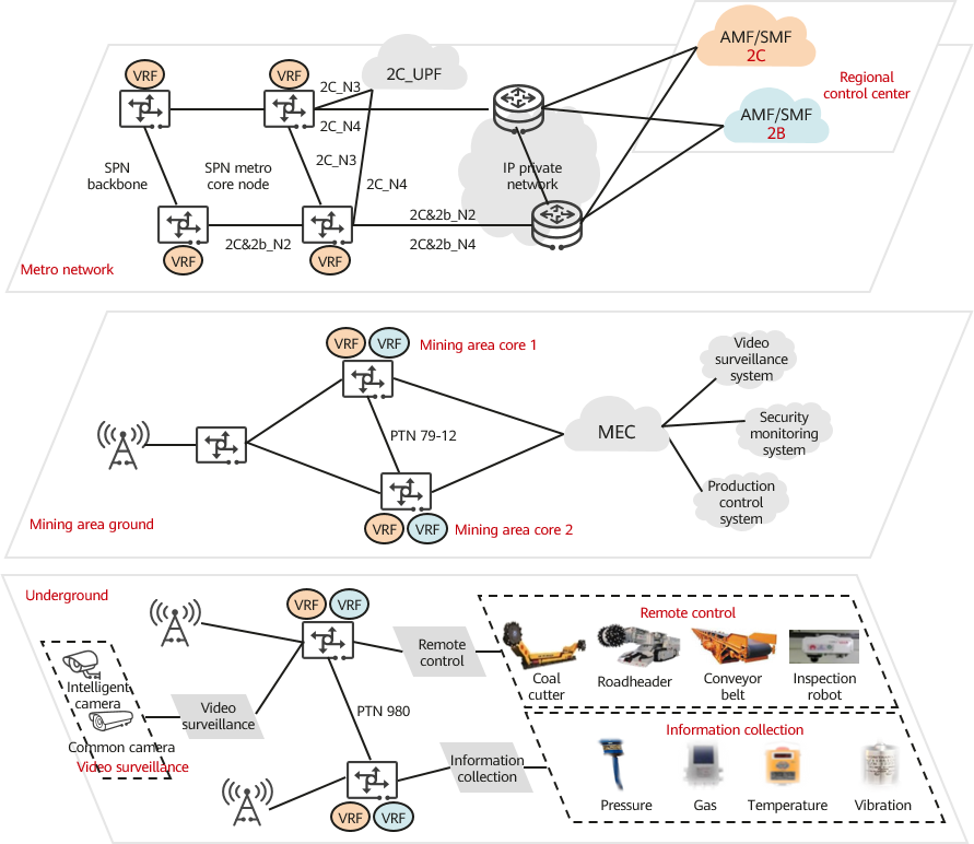
Smart mining solution
Underground surveillance, AI-based intelligent identification, underground video communication, and underground remote control services — regardless of whether they use wired or wireless communication — can be carried on the SPN, achieving intelligent slicing that features FMC.
- Wired and wireless services can be carried by different slices of the same link. These slices hard-isolate the services from each other.
- The video surveillance, remote control, and security monitoring systems are hard-isolated as they run on different slices. If any slice is congested, services in other slices are not affected.
- The bandwidth of each network slice can be dynamically scaled in or out without affecting existing services.
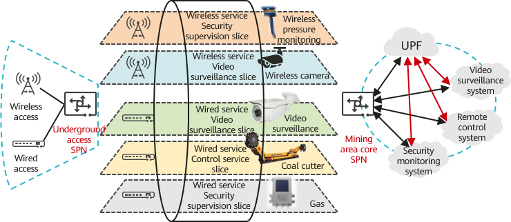
Intelligent slicing featuring FMC
SR rerouting ensures that services are always online. For SR-TP tunnels, NCE provides real-time path control capabilities, including tunnel path computation and rerouting during fault protection. If multiple points fail at the same time, rerouting on the control plane is triggered to compute a new best-effort path, achieving switching within seconds and fast service self-healing.
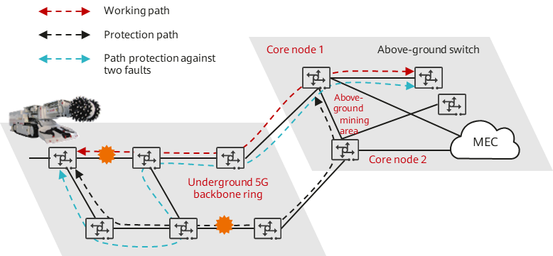
Rerouting for fast service self-healing
Ultra-HD Video Service
As big video gains traction, ultra-HD video technologies such as 4K, 8K, and VR/AR pose higher requirements on network quality. Carriers have strong network advantages and can therefore provide video services with higher quality and better user experience than Internet Over the Top (OTT) vendors can. However, traditional network architecture is designed mainly for High-Speed Internet (HSI) services. Such services feature low concurrency, and do not require very high bandwidth or low latency. Big video services are different, as they feature high concurrency and require high bandwidth, low packet loss rate, and low latency. This brings challenges to carriers in terms of bandwidth and latency.
To address the challenges, carriers can use SPN to provide network slices based on FlexE hard pipes. Each network slice carries its own services, which are isolated from other services. For example, to prevent network congestion from deteriorating IPTV service performance, carriers can deploy this service in a separate network slice, thereby isolating it from common HSI services. This approach achieves a much higher service quality than that of OTT services. The following figure shows how SPN is used in the ultra-HD video service. To monitor the performance of video traffic in this case, including the latency, bandwidth, and jitter, IFIT can be used. IFIT can also periodically collect and analyze the statistics for network adjustment and service performance assurance.
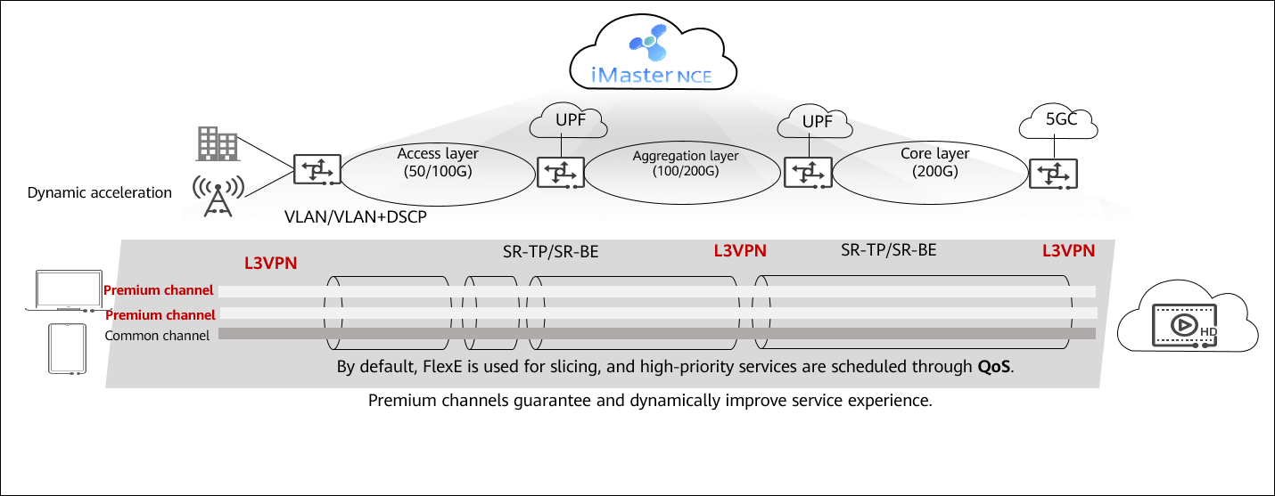
Application of SPN in the ultra-HD video service
- Author: Qian Lili
- Updated on: 2023-08-30
- Views: 2877
- Average rating:


