What Are SR-TP Tunnels?
Segment Routing Transport Profile (SR-TP) is a TP tunneling technology that uses SR as its control protocol. It enables the source node to encapsulate a series of segments that represent a topology path, thereby indicating a specific forwarding path. Compared with traditional tunnels, SR tunnels do not require transit nodes to maintain path states. This not only improves the flexibility of tunnel path adjustment, but also enhances network programmability.
How Did SR-TP Tunnels Emerge?
Segment Routing Transport Profile (SR-TP) and Segment Routing Best Effort (SR-BE) tunnels are mainstream tunnels used on slicing packet networks (SPNs). For SR-TP tunnels, you can use a controller to not only configure a label stack for the source node in order to specify a route, but also automatically deliver the label stack and associated tunnel configurations to the source node. This eliminates the need of manual configuration and delivery, better meeting the requirements for high bandwidth, low latency, and high reliability in the 5G era. The following describes how SR and TP involved in SR-TP emerged.
Evolution from SDH to PTN
Facing the rapid development of data services and the increase of demands for all-IP networks, synchronous digital hierarchy (SDH)-based multi-service transmission networks can hardly adapt to data services that often burst and require flexibility. In addition, because traditional IP networks cannot strictly ensure the quality and performance of important services, they are not suitable for carrier-class transport. Against this backdrop, next-generation transmission technologies emerge, emphasizing the transmission of packet management data, shifting the focus from audio support to data and multimedia support, and gradually leading networks into the IP transport era. Integrating IP/MPLS, Ethernet, and transport network technologies, packet transport networks (PTNs) are developed based on the ATM/Ethernet technology. In addition to effectively transmitting packet services, PTNs are also expected to inherit the key characteristics of traditional transport networks, such as high reliability, easy operation, easy maintenance, and easy management. To meet these expectations, PTNs need to overcome two core problems, that is, how to detect a fault on a service path and how to implement service switching or protection after the fault is detected. On traditional IP and transport networks, the following technologies are used to solve the preceding problems:
- IP networks use bidirectional forwarding detection (BFD) and fast reroute (FRR) to detect service path faults and implement service switching, respectively.
- SDH networks typically use the operation, administration, and maintenance (OAM) and automatic protection switching (APS) technologies to detect service path faults and implement fault-triggered switching, respectively. Both technologies can be implemented through hardware, without occupying the forwarding resources of devices.
Aiming at using IP-based PTN devices for data transmission along with SDH-based OAM and APS technologies for fault detection and protection, the ITU-T and IETF set up a joint working team (JWT) to formulate a new packet transmission protocol — Multiprotocol Label Switching-Transport Profile (MPLS-TP). This protocol defines MPLS standards with transmission features, as indicated by "TP" in the protocol name.
Evolution from PTN to SPN
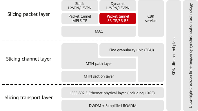
In the 5G era, a single network carries services of various industries, which have strict requirements for differentiated transport of such services. To meet these requirements, end-to-end (E2E) slices need to be deployed. By integrating packet, transport, optical-layer, and other technologies, China Mobile and Huawei worked together to propose a next-generation converged transport network architecture — SPN — based on the Ethernet kernel. Using the Ethernet transmission architecture, the SPN solution inherits, enhances, and innovates the functions of the PTN transport solution. Based on the ITU-T network model, the SPN architecture is divided into the slicing packet layer (SPL), slicing channel layer (SCL), and slicing transport layer (STL). SR-TP is deployed at the SPL to implement hierarchical transport, OAM detection, and protection for packet services.
SPN architecture
Let's look at SR, whose development is influenced by the software-defined networking (SDN) technology. The biggest difference between SR and traditional IP/MPLS technologies is that SR implements label-based forwarding through the source routing mechanism. SR divides a network path into different segments and assigns segment IDs (SIDs) to the segments and involved network nodes. The SIDs are sequentially arranged into a segment list (also called SID list), generating a forwarding path on the source node. In the forwarding plane, SR can be implemented using MPLS labels. In this case, it supports two types of tunnels, namely, SR-BE and Segment Routing Traffic Engineering (SR-TE), which are used to carry east-west and north-south traffic, respectively.
- SR-BE tunnel: This type of tunnel is implemented through IGP extensions, mainly IS-IS extensions. It features easy deployment and equal-cost multi-path (ECMP) implementation.
- SR-TE tunnel: This type of tunnel requires an SDN controller to collect network-wide topology information and compute a forwarding path from a global perspective. After completing the computation, the controller delivers a label stack that strictly matches the path to the source node. In this way, subsequent nodes only need to forward the received packet based on the top label in the stack. Transit nodes are unaware of the tunnel and do not need to maintain the tunnel state.
PTNs are evolving towards SPNs. To inherit the experience in PTN deployment and maintenance, SPNs retain the OAM and APS mechanisms in MPLS-TP. In addition, to use SR in SDN-oriented evolution, the following extensions have been defined based on SR-TE:
- On the basis of SR-TE tunnels, SR-TP has an additional label added to identify an E2E service flow. This label is a local label allocated by the sink node to the source node for E2E tunnel management.
- In terms of detection, SR-TP inherits the OAM technology used for static CR tunnels on PTNs in order to implement E2E tunnel detection.
- In terms of protection, SR-TP inherits the APS technology used for static CR tunnels on PTNs in order to implement E2E protection switching between active and standby tunnels.
To sum up, SR-TP is developed on SPNs by combining MPLS-TP on PTNs and SR-TE on IP-based networks. MPLS-TP, SR-TP, and SR-BE have their own characteristics and application scenarios, as described in the following table.
Tunneling Technology |
Number of Connections |
TE Capability |
Typical Application Scenario |
|---|---|---|---|
MPLS-TP |
Small |
Yes |
Group customer private line and PTN-SPN interworking scenarios |
SR-TP |
Medium |
Yes |
SPN-specific 5G 2C/2B north-south traffic and cloud-network private line scenarios |
SR-BE |
Large |
No |
SPN-specific 5G 2C/2B east-west traffic scenarios |
How Do SR-TP Tunnels Work?
Principles of SR-TP Tunnels
The SR-TP tunneling technology is implemented through the following process:
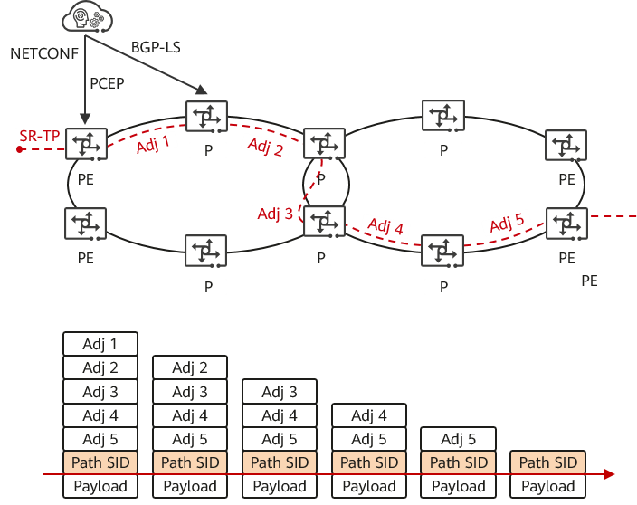
- Topology collection and label allocation: After IS-IS and SR are enabled on devices and a neighbor relationship is established between each pair of directly connected devices, a controller is used to allocate a local adjacency label (such as Adj 1/2/3/4/5 in the following figure) to each link on the network. The adjacency labels are flooded on the entire network through the IS-IS SR extension. If BGP-LS is deployed between the devices and controller, the devices run BGP-LS to collect topology information with SR labels and then report the information to the controller.
- Tunnel creation: Based on SR-TP tunnel attributes, the controller functions as a path computation element (PCE) to compute a path in a way similar to TP path computation. Then, it combines the adjacency labels of the entire path to generate a label stack, that is, the path computation result (such as Adj 1 -> Adj 2 -> Adj 3 -> Adj 4 -> Adj 5 in the following figure). Through Network Configuration Protocol (NETCONF) and Path Computation Element Communication Protocol (PCEP), the controller delivers the tunnel configuration and label stack, respectively, to the specified forwarder. The forwarder then establishes an SR-TP tunnel accordingly.
- Data forwarding: The forwarder performs label operations on the received packet according to the label stack corresponding to the SR-TP tunnel and searches for the outbound interface according to the top label. In this way, it is possible to forward the packet to the destination hop by hop. After receiving the packet, each transit node (P node) searches the adjacency label table for the corresponding outbound interface, removes the outer label, and forwards the packet to the next hop. When the outer label of the packet received by the sink node is the path SID allocated by the sink node itself, the tunnel is terminated.
SR-TP tunnel forwarding model
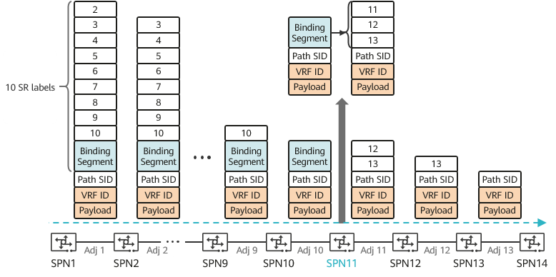
SPN devices support a label stack with a maximum of 10 adjacency labels. This means that they support tunnels with a maximum of 12 devices (including the source and sink nodes). If an SR-TP tunnel has more than 12 devices, the label stitching mechanism is used to increase the maximum number of hops supported on the tunnel. To reduce the number of labels that the source node needs to encapsulate into a packet, the controller allocates a special type of label — binding label — to the source node based on a specified transit node (such as SPN_11 in the following figure). In this way, when generating a label-based forwarding path for an SR-TP tunnel, the source node only needs to encapsulate the adjacency label (between itself and the specified transit node) and the binding label into the packet. After receiving the packet, the transit node translates the binding label to obtain the adjacency label stack between itself and the sink node, and then forwards the packet based on this label stack.
Label stitching mechanism for SR-TP tunnels
Protection Mechanism for SR-TP Tunnels
SR-TP tunnels inherit the APS and OAM mechanisms of MPLS-TP tunnels. The following describes how the protection mechanism for SR-TP tunnels works.
SR-TP APS uses the SR-TP OAM detection mechanism to detect the status of the working and protection tunnels. Specifically, the source node of a tunnel periodically sends OAM detection packets to the sink node. If the sink node does not receive such packets within a specified period, it considers that a link signal failure has occurred in the tunnel and triggers APS. In addition, the sink node notifies the APS module on the source node of the failure in order to trigger service switching on the source node, thereby implementing service protection. SR-TP APS 1:1 protection switching is triggered when any of the following conditions is met:
- The working link fails.
- Board hardware fails.
- A cold reset is performed on a board.
- A switching command is manually delivered.
- The bit error rate of an Ethernet interface exceeds the preset threshold.
If both the working and protection tunnels are faulty due to poor link quality, is there any other backup tunnel that can work?
Yes, there is: SR-TP tunnel rerouting improves tunnel reliability for key services. As an enhancement to SR-TP APS, SR-TP tunnel rerouting requires you to configure an active route and a standby route on a device. Information about both routes is written into the forwarding table. If the active route fails, the device switches traffic to the standby route based on forwarding entries. SR-TP tunnels support the following pinning modes:
- Hard pinning: In this mode, tunnel rerouting is not performed in any scenario.
- Soft pinning: In this mode, the tunnel path does not proactively respond to topology changes, and the original path is restored only after the associated tunnel fault is rectified through re-routing.
- No pinning: In this mode, path re-computation is performed based on the latest BGP topology after the original path fails.
SR-TP APS can be deployed for tunnels carrying key services, and the working and protection SR-TP tunnels can be configured to work in hard pinning and soft pinning modes, respectively.
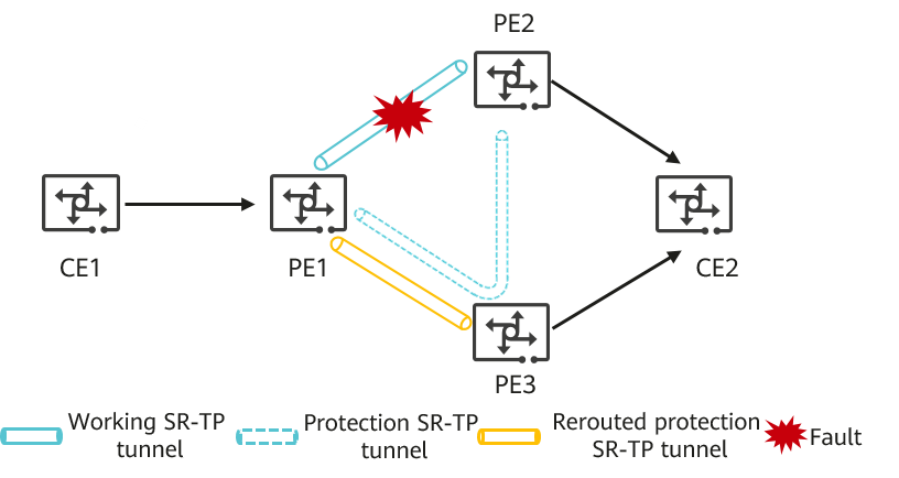
On the network shown in the following figure, an active route and a standby route are configured on PE1, and they both point to CE2. The outbound interface of the active route is configured with a working tunnel and a protection tunnel, and the outbound interface of the standby route is used for rerouting. In normal cases, the working path is CE1 -> PE1 -> PE2 -> CE2. If the link between PE1 and PE2 is faulty, PE1 detects the fault through OAM and triggers SR-TP APS to switch traffic to the protection SR-TP tunnel. As such, the path becomes CE1 -> PE1 -> PE3 -> PE2 -> CE2. If PE2 encounters a fault, the protection SR-TP tunnel fails. In this case, PE1 detects the fault through OAM and switches traffic to the rerouted protection SR-TP tunnel (the post-switching path is CE1 -> PE1 -> PE3 -> CE2). Because the protection tunnel works in soft pinning mode, the original working tunnel can be restored after the fault is rectified.
SR-TP tunnel protection
For more information about APS, see APS Protection.
- Author: Qian Lili
- Updated on: 2023-10-07
- Views: 1248
- Average rating:


